
A new type of flapping wing propulsion device and its working process

A propulsion device, a new type of technology, applied in the direction of propulsion-based emission reduction, transportation and packaging, helicopters, etc., can solve the problem of no optimization space, etc., and achieve the effect of compact structure, improved propulsion efficiency, and reduced energy dissipation

Active Publication Date: 2022-07-12
CHINA SHIP SCIENTIFIC RESEARCH CENTER (THE 702 INSTITUTE OF CHINA SHIPBUILDING INDUSTRY CORPORATION)
View PDF0 Cites 0 Cited by
  • Summary
  • Abstract
  • Description
  • Claims
  • Application Information

AI Technical Summary

Problems solved by technology

[0004] The traditional oscillating wing propulsion method is mainly composed of heave motion in the vertical direction and pitching motion around its own rotation axis. The oscillating wing based on the above-mentioned traditional motion method can only obtain a maximum of 60% under the optimal combination of motion parameters. Left and right propulsion efficiency, currently there is no room for higher optimization

Method used


Image

  • A new type of flapping wing propulsion device and its working process
  • A new type of flapping wing propulsion device and its working process
  • A new type of flapping wing propulsion device and its working process

Examples


Embodiment Construction

[0035] The specific embodiments of the present invention will be described below with reference to the accompanying drawings.

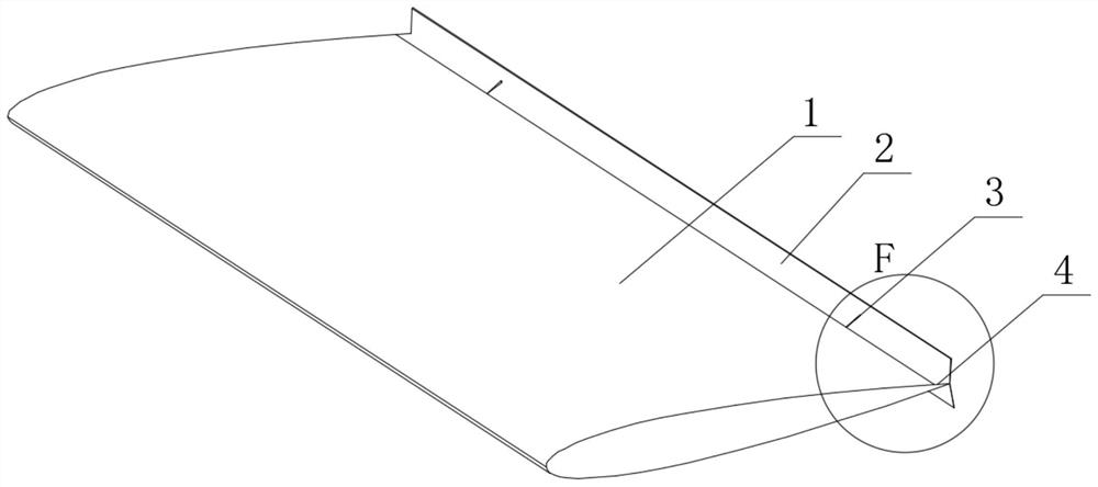
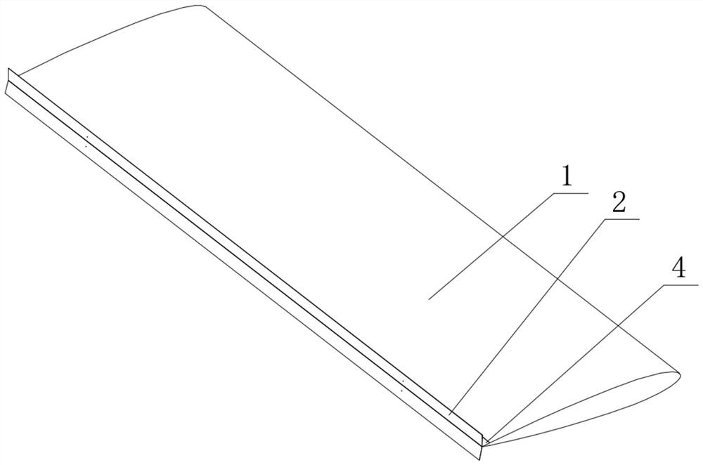
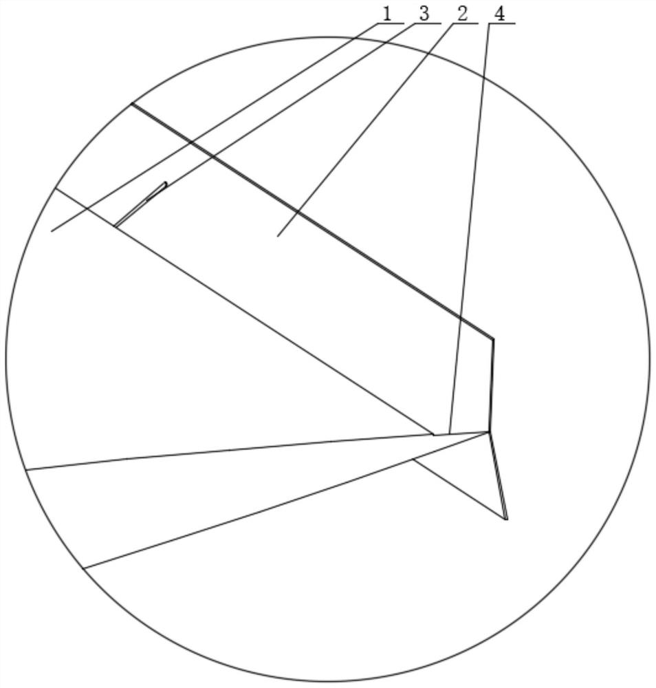
[0036] like Figure 1-Figure 8 As shown, the novel flapping wing propulsion device of this embodiment includes a flapping wing body 1, a pair of tail sealing plates 2 are hinged at the trailing edge of the flapping wing body 1, and a A plurality of retracting rods 3 are installed between the tail sealing plate 2 and the stepped surface 4, and the movement of the retracting rods 3 controls the opening and closing of the tail sealing plate 2.

[0037] The flapping wing body 1 adopts the NACA0012 profile airfoil with an aspect ratio of 3.0.

[0038] The length of the tail cover plate 2 is equal to the extension of the flap body 1 .

[0039] The height of the tail cover 2 is equal to the maximum thickness of the flap body 1 .

[0040] When the tail sealing plate 2 is opened, the tail sealing plate 2 is perpendicular to the step surface 4;

[0041] The...


PUM


Abstract

A novel flapping wing propulsion device and its working process include a flapping wing main body, a pair of tail sealing plates are hinged at the trailing edge of the flapping wing main body, and a step is respectively provided on the upper surface and the lower surface of the tail part of the flapping wing main body, and forms a step. A plurality of retracting rods are installed between the stepped surface, the tail sealing plate and the stepped surface, and the movements of the retracting rods control the opening and closing of the tail sealing plate. The tail sealing plate can be adaptively adjusted according to the movement position of the flapping wing. On the one hand, the existence of the tail sealing plate greatly increases the pressure difference between the upper and lower surfaces of the flapping wing, and the corresponding lift is also significantly increased. There is an angle of attack in the horizontal direction, so the component force of the lift force increased in the vertical direction in the horizontal direction is also increased, so the propulsion characteristics of the flapping wing are improved; The flow field characteristics are improved, the flow separation at the trailing edge of the flapping wing is gradually slowed down, the energy dissipation is reduced, and the system input power is greatly reduced.

Description

technical field [0001] The invention relates to the technical field of propulsion equipment, in particular to a novel flapping wing propulsion device and a working process. Background technique [0002] Flapping wing propulsion is another propulsion method that is different from traditional rotating machinery (propellers, turbine engines) and jet propulsion. [0003] With the rise of research on micro air vehicles and underwater robots in recent years, this propulsion method has shown more and more advantages. This is mainly due to the low efficiency of traditional propeller propulsion at low Reynolds number, and this flapping unsteady motion can not only achieve high lift that cannot be achieved by fixed wings, but also has a certain propulsion efficiency compared to traditional methods. superiority. Birds flying in the sky and fish swimming underwater all use such unsteady motions to achieve propulsion, and it is the excellent flying and swimming capabilities of these cr...

Claims


Application Information

Patent Timeline
Patent Type & Authority Patents(China)
IPC IPC(8): B64C33/02
CPCB64C33/02Y02T70/5236
Inventor 李永成陈纪军潘子英
Owner CHINA SHIP SCIENTIFIC RESEARCH CENTER (THE 702 INSTITUTE OF CHINA SHIPBUILDING INDUSTRY CORPORATION)
Learn More