Antenna for wireless charging system
What is Al technical title?
Al technical title is built by PatSnap Al team. It summarizes the technical point description of the patent document.
A wireless charging and antenna technology, applied in antennas, charging stations, resonant antennas, etc., can solve problems such as low energy transmission efficiency, low efficiency, and unsatisfactory energy
Pending Publication Date: 2021-11-19
HUMAVOX
View PDF3 Cites 0 Cited by
Summary
Abstract
Description
Claims
Application Information
AI Technical Summary
This helps you quickly interpret patents by identifying the three key elements:
Problems solved by technology
Method used
Benefits of technology
Problems solved by technology
However, the process is usually inefficient and wastes a lot of energy
In addition, the coupling process itself is a very strict process, and the coupling between the transmitting antenna and the receiving antenna is sensitive and unstable, and may vary with the positioning of the transmitting unit and receiving unit of the wireless charging system and the positioning of the transmitting antenna and receiving antenna. Antenna design changes vary with
In addition, the coupling process may be further affected by the presence of other components around as well as environmental conditions
These factors lead to inefficient energy transfer between the transmitting unit and the receiving unit
Therefore, there remains an unmet need for receive antennas and transmit antennas for electromagnetic energy transfer systems that facilitate coupling and energy efficiency between the transmit and receive units of wireless charging systems
Method used
Image
Click on the blue label to locate the original text in one second.
Reading with bidirectional positioning of images and text.
Examples
Embodiment Construction
[0045] Wireless charging systems and wireless charging devices are well known in the art. Some examples of such charging systems and devices using electromagnetic energy for charging are described in detail in International Patent Publication Nos. WO2013 / 118116, WO2013 / 179284 and WO2015 / 022690 by the same inventor, all of which are incorporated herein by reference.
[0046] Although various features of the disclosure may be described in the context of a single implementation, these features may also be provided separately or in any suitable combination. Conversely, although the disclosure may, for clarity, be described herein in the context of separate implementations, the disclosure may also be implemented in a single implementation. Furthermore, it should be understood that the present disclosure can be carried out or practiced in various ways, and that the present disclosure can be implemented in embodiments other than the exemplary embodiments described below. The descrip...
PUM
Abstract
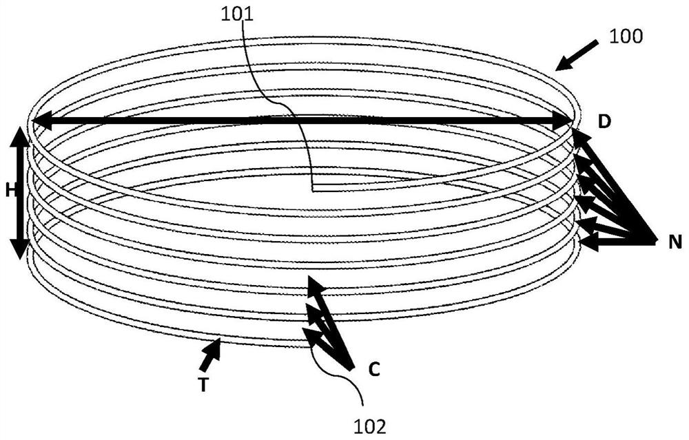
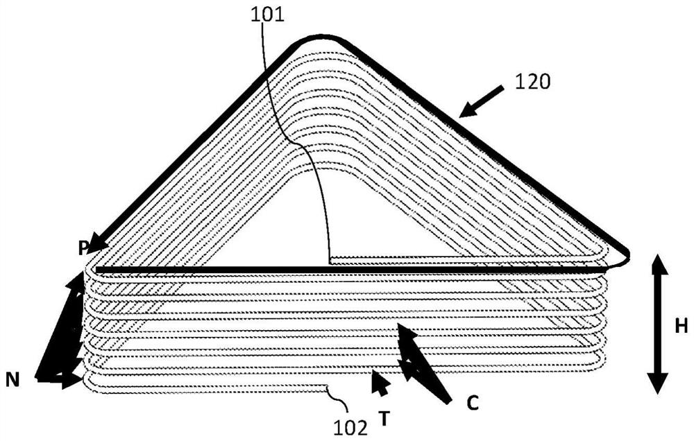
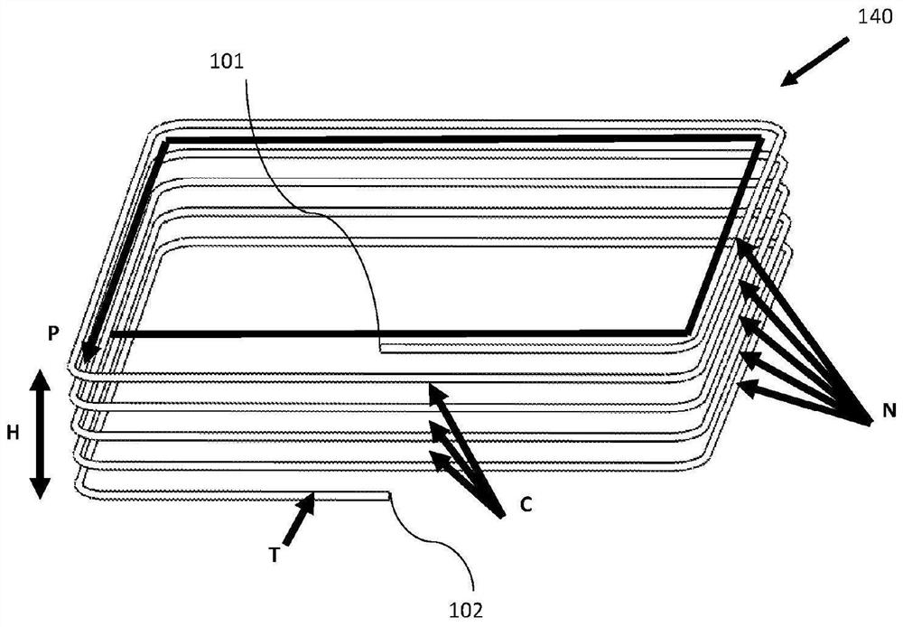
This invention is directed to antenna for wireless charging systems configured and operable to create strong electromagnetic near fields in a designated volume and by that to improve the coupling between a transmitting antenna and a receiving antenna of a wireless charging system, which improves the efficiency level of the electromagnetic energy transfer between said transmitting and receiving antennas of a wireless charging system, the antenna comprising a conductive material shaped to form two or more revolutions, each revolution adjacent to the previous revolution, wherein each of said revolution having a geometric shape. The antenna is further comprising a ground plane, wherein said formed conductive material is adapted to confine the electromagnetic near field distribution into a charging zone relative to the ground plane.
Description
[0001] Cross References to Related Applications [0002] This PCT application claims priority from the following: U.S. Provisional Application No. 62 / 770,762 filed November 22, 2018 and titled "Wireless Charging Device"; U.S. Provisional Application No. 62 / 788,889 filed in 2019 Filed January 6; U.S. Provisional Application No. 62 / 788,236, filed January 4, 2019, entitled "Antenna for Wireless Charging System"; U.S. Provisional Application No. 62 / 788,282, filed January 4, 2019 62 / 788,705, filed on January 4, 2019, entitled "Cup Holder For Wireless Charging" Cupholder for Wireless Charging)”; U.S. Provisional Application No. 62 / 788,717, filed Jan. 4, 2019, entitled “Toolbox For Wireless Charging”; U.S., filed Jan. 4, 2019 Provisional Application No. 62 / 788,728, entitled "Head Phone Case For Wireless Charging"; Provisional Application No. 62 / 788,731, filed January 4, 2019, entitled "Mobile Device Case For Wireless Charging (Mobile Device Box for Wireless Charging)"; Provisional Ap...
Claims
Application Information
Patent Timeline
Application Date:The date an application was filed.
Publication Date:The date a patent or application was officially published.
First Publication Date:The earliest publication date of a patent with the same application number.
Issue Date:Publication date of the patent grant document.
PCT Entry Date:The Entry date of PCT National Phase.
Estimated Expiry Date:The statutory expiry date of a patent right according to the Patent Law, and it is the longest term of protection that the patent right can achieve without the termination of the patent right due to other reasons(Term extension factor has been taken into account ).
Invalid Date:Actual expiry date is based on effective date or publication date of legal transaction data of invalid patent.