
Structure of three-unit mirror image gliding antenna and design method of signal distribution unit

A technology for signal distribution and design methods, applied in antennas, antenna parts, design optimization/simulation, etc., can solve problems such as the single structure of M-type glide antennas, improve signal quality, improve anti-interference performance, and improve linearity Effect

Pending Publication Date: 2020-11-03
CICIL AVIATION HUADONG NAVIGATION MANAGEMENT EQUIP INSTALLATION DEPT
View PDF0 Cites 0 Cited by
  • Summary
  • Abstract
  • Description
  • Claims
  • Application Information

AI Technical Summary

Problems solved by technology

[0007] The present invention aims to provide a three-element antenna image glide antenna structure and a design method of a signal distribution unit, so as to solve the problem of single structure and large size of the M-type glide antenna

Method used


Image

  • Structure of three-unit mirror image gliding antenna and design method of signal distribution unit
  • Structure of three-unit mirror image gliding antenna and design method of signal distribution unit
  • Structure of three-unit mirror image gliding antenna and design method of signal distribution unit

Examples


Embodiment Construction

[0037] Below in conjunction with the drawings, preferred embodiments of the present invention are given and described in detail.

[0038] The structure of the three-element image glide antenna of the present invention and the design method of the signal distribution unit comprise the following steps:

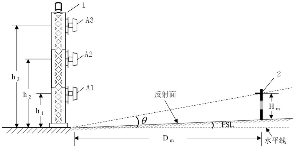
[0039] Step S1: if figure 1 As shown, determine the height of the three antennas of the upper antenna A3, the middle antenna A2 and the lower antenna A1 of the target antenna assembly 1;

[0040] Among them, the heights of the upper antenna A3, the middle antenna A2 and the lower antenna A1 are h 3 , h 2 , h 1 , the height h of the upper antenna A3 3 Height h from lower antenna A1 1 It can be changed, but there is a mutual constraint relationship, which requires that the sum of the heights of the upper antenna A3 and the lower antenna A1 is equal to twice the height of the middle antenna A2, namely:

[0041]

[0042] Said step S1 comprises:

[0043] Step S11: Determine...


PUM


Abstract

The invention provides a structure of a three-unit mirror image gliding antenna and a design method of a signal distribution unit. The design method comprises the following steps: determining the heights of three antennas; determining the position of a near-field monitoring antenna; determining the relative phase and amplitude ratio of CSB signals of the three antennas; determining the relative phase and amplitude proportion of SBO signals of the three antennas, and taking a modulation degree difference signal value with the elevation angle of 0.88 theta as a first calibration value, wherein theta is a glide angle; taking the first calibration value as the amplitude ratio of the SBO signal of the middle antenna to the CSB signal of the lower antenna; and determining the relative phase andthe amplitude ratio of CLR signals of the lower antenna and the upper antenna, and determining the amplitude ratio of the CLR signals to the CSB signals. According to the design method, through optimization design of the CSB, SBO and CLR signals, the space radiation signal quality can be effectively improved, the linearity of the space synthesis signal modulation degree difference is improved, theanti-interference performance is improved, and the total height of the antennas is changed according to actual needs.

Description

technical field [0001] The invention relates to antenna technology, in particular to a mirrored glide antenna structure for radio navigation. [0002] technical background [0003] Navigation equipment provides landing guidance signals for aircraft, which plays an important role in traditional approach methods. The approach methods include visual approach, non-precision approach and precision approach. Among them, the glide beacon can provide precision approach. The quality requirements of the external field signal radiated by its equipment are also very strict. For aviation accidents, the accident rate of aircraft during take-off and landing ranks first. Since the space signal radiated by the glide beacon provides vertical guidance information for aircraft landing, the research on the structure of the glide antenna and the relationship between signal distribution is very important. appears to be particularly important. [0004] Divided from the number of antennas, at prese...

Claims


Application Information

Patent Timeline
Patent Type & Authority Applications(China)
IPC IPC(8): G06F30/20H01Q1/12H01Q3/02
CPCG06F30/20H01Q1/1264H01Q3/02
Inventor 陆冉菁何勇李铭佳杨立钒瞿淳清解皓杰白媛温峻峰古杰
Owner CICIL AVIATION HUADONG NAVIGATION MANAGEMENT EQUIP INSTALLATION DEPT
Learn More