Environment-friendly construction waste crusher

A construction waste and pulverizer technology, applied in grain processing and other directions, can solve the problems of insufficient technology, reduce the counterattack force of the counterattack plate, and unfavorable scrap discharge, so as to improve the crushing effect and efficiency, reduce the recoil force and vibration force, reduce the Effects of mechanical damage

Active Publication Date: 2021-11-23
NANJING KISEN INT ENG
View PDF9 Cites 1 Cited by
  • Summary
  • Abstract
  • Description
  • Claims
  • Application Information

AI Technical Summary

Problems solved by technology

[0003] Most of the current construction waste pulverizers use hammer pulverizers for pulverization. Due to the imperfect technology of the existing hammer pulverizers, the distance between the hammer heads is too large, so that when the construction waste is impacted in the pulverization chamber , Large pieces of construction waste can still be impacted. When the waste is crushed to a certain extent, the debris located between the hammer head and the hammer head cannot be hit by the hammer head, resulting in the phenomenon that the crushing is not enough and cannot be discharged through the sieve plate. It will cause debris to accumulate, which is not conducive to the discharge of debris, and the existing hammer mills are equipped with counterattack plates, and there is a certain distance between the counterattack plate and the hammer head. When the impact plate collides, the distance between the impact plate and the hammer head is fixed, and the quality of different construction wastes is different. If the quality of the construction waste is small, the large distance will reduce the impact force of the impact plate, thereby reducing the crushing efficiency and effect of construction waste

Method used


Image

  • Environment-friendly construction waste crusher
  • Environment-friendly construction waste crusher
  • Environment-friendly construction waste crusher

Examples


Embodiment 1

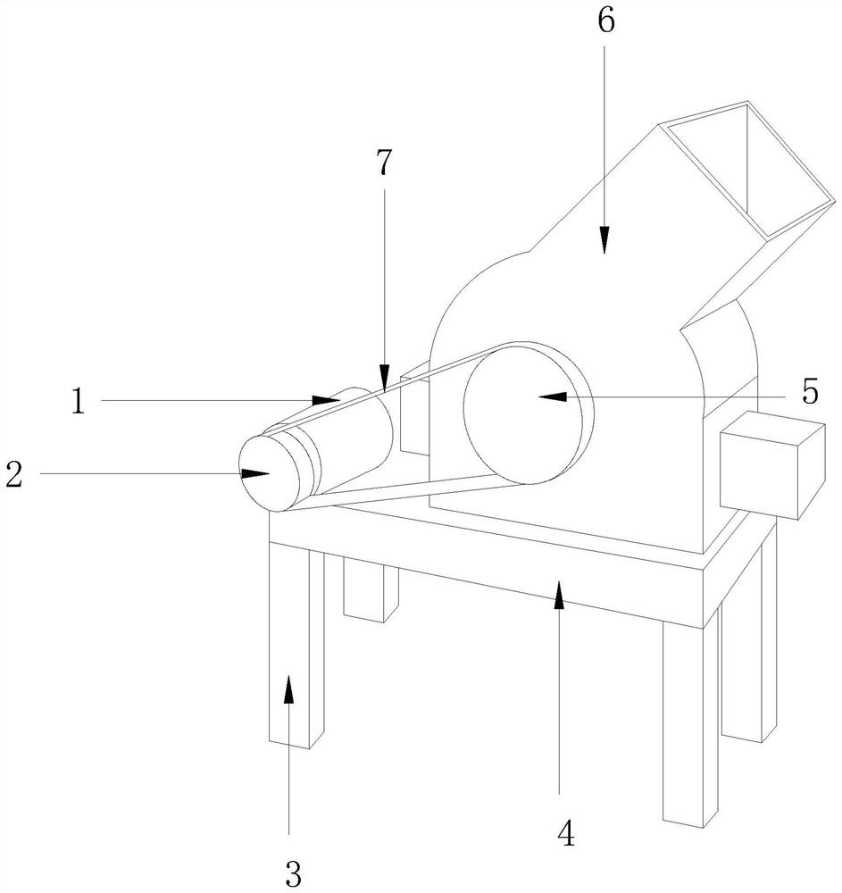
[0028] Such as figure 1 As shown, the present invention provides a technical solution of an environmentally friendly construction waste shredder: its structure includes a motor 1, a first transmission wheel 2, a supporting foot column 3, a base 4, a second transmission wheel 5, a shredder 6, and a transmission belt 7. A base 4 is installed on the top of the supporting foot column 3, and a motor 1 is provided on one side of the top of the base 4, and the shaft of the motor 1 is connected with the first transmission wheel 2, and the first transmission wheel 2 Via the transmission belt 7 and the second transmission wheel 5, the second transmission wheel 5 is connected with the pulverizer 6.

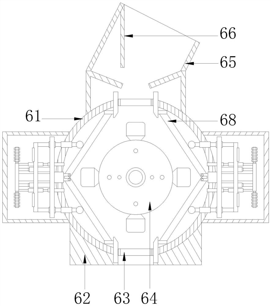
[0029] Such as Figure 2-3As shown, the pulverizer 6 includes a counterattack material frame 61, a pulverizer shell 62, a sieve plate 63, a crushing device 64, a feed port 65, a baffle plate 66, and a chute plate 67. There is a pulverizing device 64, and a sieve plate 63 is arranged below...

Embodiment 2

[0035] Such as Figure 1-Figure 8 As shown, the present invention provides a technical solution of an environmentally friendly construction waste shredder: its structure includes a motor 1, a first transmission wheel 2, a supporting foot column 3, a base 4, a second transmission wheel 5, a shredder 6, and a transmission belt 7. A base 4 is installed on the top of the supporting foot column 3, and a motor 1 is provided on one side of the top of the base 4, and the shaft of the motor 1 is connected with the first transmission wheel 2, and the first transmission wheel 2 Via the transmission belt 7 and the second transmission wheel 5, the second transmission wheel 5 is connected with the pulverizer 6.

[0036] The pulverizer 6 includes a counterattack material frame 61, a pulverizer shell 62, a sieve plate 63, a pulverizing device 64, a feed port 65, a baffle plate 66, and a chute plate 67, and the pulverizer shell 62 is provided with a pulverizing device. 64. A sieve plate 63 is...

Embodiment 3

[0047] Such as figure 1 , figure 2 , Figure 9 , Figure 10 As shown, the present invention provides a technical solution of an environmentally friendly construction waste shredder: the structure includes a motor 1, a first transmission wheel 2, a supporting foot column 3, a base 4, a second transmission wheel 5, a shredder 6, and a transmission belt 7 , a base 4 is installed on the top of the supporting foot column 3, a motor 1 is provided on one side of the top of the base 4, the shaft of the motor 1 is connected with the first transmission wheel 2, and the first transmission wheel 2 passes through The transmission belt 7 is movably matched with the second transmission wheel 5, the second transmission wheel 5 is connected with the pulverizer 6, and the second transmission wheel 5 is connected with the transmission shaft 64a.

[0048] The pulverizer 6 includes a counterattack material frame 61, a pulverizer shell 62, a sieve plate 63, a pulverizer 64, a feed port 65, a b...


PUM


Abstract

The invention discloses an environment-friendly construction waste crusher. The environment-friendly construction waste crusher structurally comprises a motor, a first transmission wheel, a supporting leg column, a base, a second transmission wheel, a crusher body and a transmission belt, and has the beneficial effects that through the structural design of a sliding groove disc and a push rod, the sliding groove disc serves as a static part, the push rod serves as a dynamic part, a hammer head has the left-right displacement function in the rotating process, the hammer head can comprehensively crush the construction waste in a crushing cavity, crushing of the construction waste is more sufficient, crushing and discharging of the construction waste are facilitated, a counterattack adjusting device can control the distance matching degree of a counterattack plate and the hammer head by controlling stretching and retracting of a hydraulic telescopic rod, and the crushing effect of the construction waste is improved; and meanwhile, the crushing size and the crushing speed of the construction waste can be accurately controlled, the recoil force and the vibration force of the counterattack plate are reduced, the crushing effect is further enhanced, and meanwhile mechanical damage to the hydraulic telescopic rod and the motor is reduced.

Description

technical field [0001] The invention relates to the field of garbage disposal, more precisely, it is an environment-friendly construction garbage shredder. Background technique [0002] Construction waste refers to spoils, waste materials, steel bars, glass and other wastes generated during the construction, laying or demolition, and repair of various buildings, structures, and pipe networks. The construction waste shredder can turn construction waste into treasure. First, the construction waste can be used to see whether the material itself needs to be shredded. [0003] Most of the current construction waste pulverizers use hammer pulverizers for pulverization. Due to the imperfect technology of the existing hammer pulverizers, the distance between the hammer heads is too large, so that when the construction waste is impacted in the pulverization chamber , Large pieces of construction waste can still be impacted. When the waste is crushed to a certain extent, the debris l...

Claims


Application Information

Patent Timeline
Patent Type & Authority Applications(China)
IPC IPC(8): B02C13/09B02C13/28B02C13/282B02C13/30
CPCB02C13/095B02C13/28B02C13/282B02C13/30B02C2013/2825B02C2201/06
Inventor 郑长顺
Owner NANJING KISEN INT ENG
Why Eureka
Try Eureka