A vibrating platform cutting auxiliary device for multi-wire cutting machine

A multi-wire cutting machine and vibrating platform technology, applied in fine working devices, manufacturing tools, stone processing equipment, etc., can solve the problems of wire breakage, increased processing costs and safety risks, and unsatisfactory surface quality, and achieve high stability. The effect of frequency vibration, improving processing quality and work efficiency

Active Publication Date: 2022-07-19
唐山晶玉科技股份有限公司
View PDF19 Cites 0 Cited by
  • Summary
  • Abstract
  • Description
  • Claims
  • Application Information

AI Technical Summary

Problems solved by technology

[0003] In the existing multi-wire cutting processing technology, the surface line mark of the workpiece is relatively obvious, the surface quality is not ideal, and it is not conducive to the post-processing of the product; in the existing multi-wire cutting processing technology, the method of optimizing process parameters is generally used to improve processing efficiency: Such as increasing the speed of the wire, increasing the tension of the cutting wire, reducing the diameter of the cutting wire, etc., the above methods to improve the processing efficiency will increase the risk of line interruption in the processing process, resulting in an increase in processing costs and safety risks; at the same time, when the processing efficiency When it is raised to a certain critical value, optimizing the process parameters cannot further improve its processing efficiency and surface quality of the workpiece

Method used

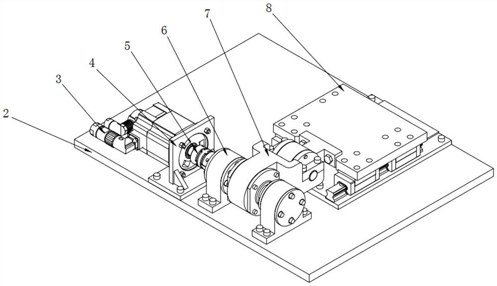
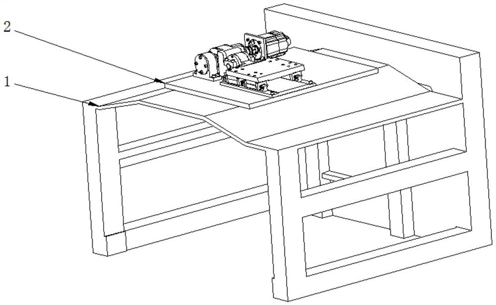
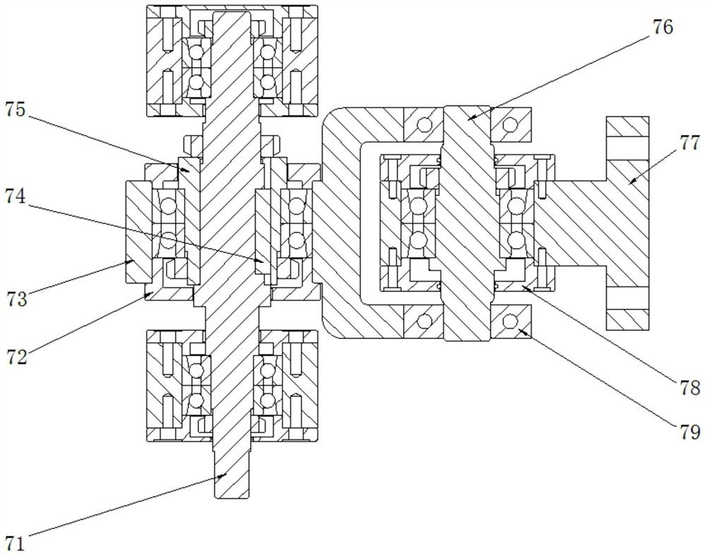

Image

  • A vibrating platform cutting auxiliary device for multi-wire cutting machine
  • A vibrating platform cutting auxiliary device for multi-wire cutting machine
  • A vibrating platform cutting auxiliary device for multi-wire cutting machine

Examples


Embodiment Construction

[0018] In order to illustrate the embodiments of the present invention or the technical solutions in the prior art more clearly, the following briefly introduces the accompanying drawings that need to be used in the description of the embodiments or the prior art. Obviously, the accompanying drawings in the following description These are some embodiments of the present invention. For those of ordinary skill in the art, other drawings can also be obtained according to these drawings without creative efforts.

[0019] It should be noted that in the description of the present invention, the terms "upper", "lower", "top", "bottom", "one side", "the other side", "left", "right", etc. The orientation or positional relationship is based on the orientation or positional relationship shown in the drawings, and is only for the convenience of describing the present invention and simplifying the description, and does not mean that a device or element must have a specific orientation, be c...


PUM


Abstract

The invention relates to a vibrating platform cutting auxiliary device for a multi-wire cutting machine, comprising a bottom plate, a motor, a motor support, a coupling, two bearing seats, a vibration component and a sliding platform; the output shaft of the motor is connected to the vibration The drive shaft of the component is connected by a coupling; the drive shaft and the eccentric sleeve are connected by a key to drive the eccentric sleeve to rotate; the vibration part is sleeved on the outer surface of the eccentric sleeve; the guide rail mounting plate is fixed on the base, the guide rail Symmetrically arranged on both sides of the guide rail mounting plate; the sliding block is fixedly installed at the bottom of the worktable, so that the worktable can reciprocate along the guide rail; the T-shaped connector is fixedly connected with the worktable; the invention can make the workpiece to be cut along the tangent line The direction of high-frequency vibration, so as to achieve the purpose of improving the workpiece processing quality and work efficiency.

Description

technical field [0001] The invention relates to the technical field of multi-wire cutting equipment, in particular to a vibrating platform cutting auxiliary device for a multi-wire cutting machine. Background technique [0002] Multi-wire cutting is a new type of cutting process that uses the high-speed reciprocating motion of metal wires to bring abrasives into the semiconductor processing area for grinding, and cuts hard and brittle materials such as semiconductors into hundreds of thin slices at one time. At present, CNC multi-wire cutting has gradually replaced the traditional inner circle cutting and has become the main way of cutting hard and brittle materials. Multi-wire cutting machine equipment is widely used in the field of semiconductor material processing. [0003] In the existing multi-wire cutting processing technology, the surface line marks on the workpiece are relatively obvious, the surface quality is not ideal, and it is not conducive to the post-processi...

Claims


Application Information

Patent Timeline
Patent Type & Authority Patents(China)
IPC IPC(8): B28D5/04B28D7/00
CPCB28D5/045B28D5/0058
Inventor 董志奎赵延恒张琛璞刘梓良梁傲吴尚常龙邢珂
Owner 唐山晶玉科技股份有限公司
Why Eureka
Try Eureka