Building construction dustproof net convenient to lay
A technology for building construction and dust-proof nets, applied in the field of dust-proof nets, can solve the problems of easy dumping of dust-proof nets, inconvenient collection of dust-proof nets, cumbersome laying process of dust-proof nets, etc., to achieve the effect of preventing dumping and facilitating secondary use
- Summary
- Abstract
- Description
- Claims
- Application Information
AI Technical Summary
Problems solved by technology
Method used
Image
Examples
Embodiment 1
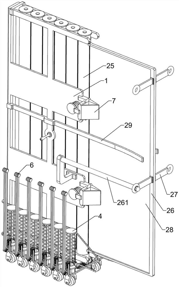
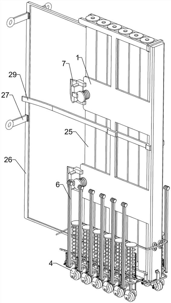
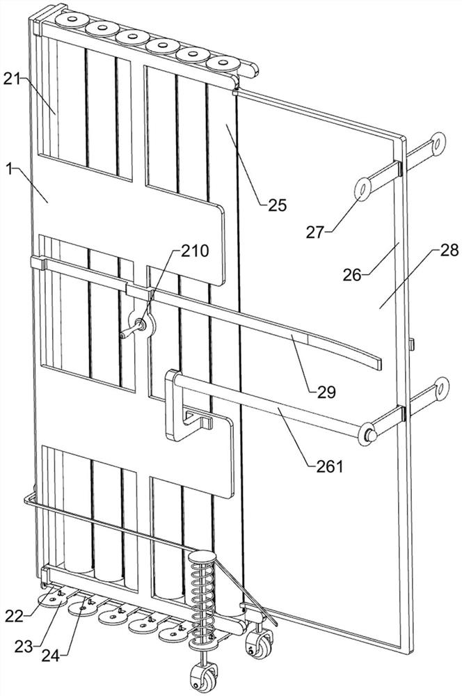
[0053] A kind of dust-proof net that is convenient to lay for building construction, such as figure 1 , figure 2 , image 3 , Figure 4 , Figure 5 , Figure 6 , Figure 7 , Figure 8 , Figure 9 and Figure 10 As shown, it includes a support converging frame 1, a fixed connection block 21, a first telescopic rod 22, a sliding support seat 23, a second telescopic rod 24, a support converging tube 25, a C-shaped support frame 26, a sleeve rod 261, an installation Frame 27, fixed dust-proof net 28, winding limit frame 29, push handle 210, retractable arrangement component 3 and ground support component 4, and a fixed connection block 21 is fixedly connected to the left side of the support converging frame 1 to support converging The inside of the frame 1 is linearly distributed and sleeved with six support tubes 25, and the bottom of the support tubes 25 is connected with a sliding support seat 23 by bolts, and the sliding support seat 23 on the left side is connected w...
Embodiment 2
[0059] On the basis of Example 1, such as Figure 11 and Figure 12 As shown, it also includes a locking assembly 5, which is used to automatically lock the rotating wheel 42. The locking assembly 5 is arranged on the sliding support seat 23. The locking assembly 5 replaces the manual push of the sliding slotted bracket 46 to lock the rotating wheel 42. Component 5 includes support slide rail frame 51, sliding T-shaped frame 52, inclined-plane push frame 53, connecting rod 54, push post 55, band bar rack 56 and gear frame 57, and the bottom of sliding support seat 23 is fixedly connected with support slide. The rail frame 51, the bottom of the supporting rail frame 51 is slidingly connected with a sliding T-shaped frame 52, the sliding T-shaped frame 52 is fixedly connected with an inclined-plane push frame 53, and the sliding T-shaped frame 52 is connected with a symmetrical rotation connection for power transmission. Rod 54, the bottom of the sliding magnetic block 44 is fi...
Embodiment 3
[0062] On the basis of Example 2, such as Figure 13 , Figure 14 , Figure 15 and Figure 16As shown, it also includes an anti-dumping assembly 6, which is arranged on the sliding support seat 23. The anti-dumping assembly 6 is used to prevent the equipment from toppling over, and plays a role in supporting the equipment more stably. The anti-dumping assembly 6 includes a sliding Rail support frame 61, sliding block 62, first return spring 621, swing lever 63, special-shaped push frame 64, U-shaped connecting frame 65, sliding slotting frame 66, second return spring 67, band bar swing support frame 68, Rocking arm 69, support limit frame 691, special-shaped slotted frame 610 and sliding perforated ring 611, slide rail support frame 61 is symmetrically fixed on the sliding support seat 23, slide rail support frame 61 is slidably connected with sliding block 62 , the first return spring 621 is connected between the sliding block 62 and the slide rail support frame 61, the si...
PUM
 Abstract
Description
Claims
Application Information
 - R&D
- Intellectual Property
- Life Sciences
- Materials
- Tech Scout
- Unparalleled Data Quality
- Higher Quality Content
- 60% Fewer Hallucinations
Browse by: Latest US Patents, China's latest patents, Technical Efficacy Thesaurus, Application Domain, Technology Topic, Popular Technical Reports.
© 2025 PatSnap. All rights reserved.Legal|Privacy policy|Modern Slavery Act Transparency Statement|Sitemap|About US| Contact US: help@patsnap.com


