
Water heating system capable of automatically adjusting energy and control method thereof

A water heating system and automatic adjustment technology, applied in the field of communication, can solve the problems of unfavorable energy saving, room temperature and flow changes can not be fed back in real time, and achieve the effect of precise temperature control

Pending Publication Date: 2021-11-23
张晓菊
View PDF7 Cites 0 Cited by
  • Summary
  • Abstract
  • Description
  • Claims
  • Application Information

AI Technical Summary

Problems solved by technology

Changes in room temperature and flow cannot be fed back to the hot water supply system in real time, and the hot water supply system generally adjusts the outlet water temperature and flow according to a constant value or manually, which is not conducive to energy saving

Method used


Image

  • Water heating system capable of automatically adjusting energy and control method thereof
  • Water heating system capable of automatically adjusting energy and control method thereof
  • Water heating system capable of automatically adjusting energy and control method thereof

Examples


Embodiment 1

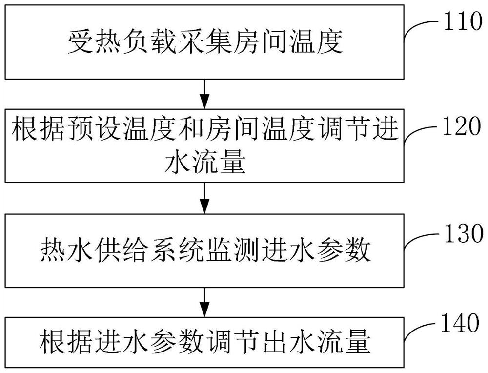
[0034] Such as figure 1 As shown, Embodiment 1 of the present application provides a water heating system control method that can automatically adjust energy, including:

[0035] Step 110, the heating load collects room temperature;

[0036] The heating load includes multiple indoor room terminal equipment. The terminal equipment collects the temperature in the corresponding room. Specifically, the current room temperature can be collected through the temperature measurement module installed in the terminal equipment, or by setting a temperature sensor connected to the terminal equipment separately To collect the temperature in the room.

[0037] Step 120, adjusting the inflow flow according to the preset temperature and the room temperature;

[0038] In the embodiment of the present application, adjusting the inflow flow according to the preset temperature and the room temperature specifically includes the following sub-steps:

[0039] Step 121, constructing a relationship...

Embodiment 2

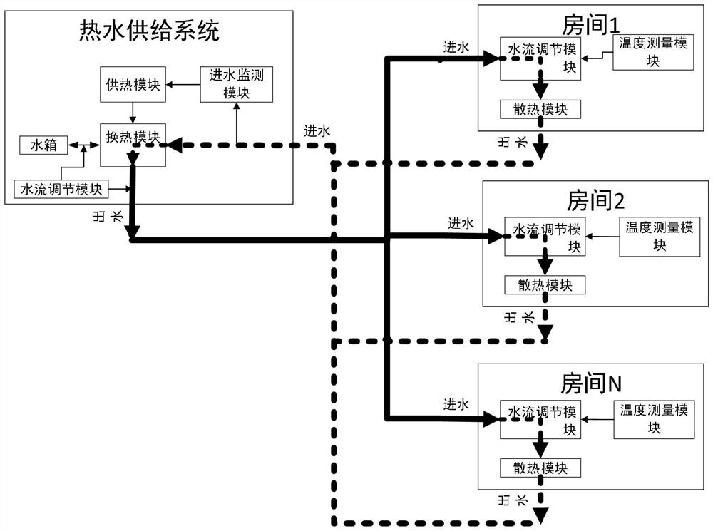
[0063] Such as figure 2 As shown, Embodiment 2 of the present application provides a water heating system that can automatically adjust energy, including a hot water supply system and a heating load. The hot water supply system can be a unified water supply system for a certain area, or it can be a water temperature control system set up for each household or several households. The heating load is the terminal equipment of each heated room in the house. The internal terminal equipment transfers heat through the water pipeline connection, and the communication module transmits signals between the hot water supply system and the heated load. Both the heating load and the hot water supply system are devices that can work independently and have independent control capabilities. The hot water supply system adjusts the incoming water flow according to the temperature and water flow fed back by the heating load in real time to control the temperature of the heating load.

[0064]...


PUM


Abstract

The invention discloses a water heating system capable of automatically adjusting energy and a control method thereof. The system comprises a hot water supply system and a heated load, wherein the hot water supply system and the heated load are connected through a water conveying pipeline to transfer heat, and signals are transmitted between the hot water supply system and the heated load through a communication module; the hot water supply system comprises a water flow adjusting module, a heat supply module, a heat exchange module, a water inlet monitoring module and a water tank; and the heated load comprises a water flow adjusting module, a temperature measuring module and a heat dissipation module. According to the invention, an outlet water temperature and flow can be adjusted in real time according to temperature and flow information of all rooms (tail ends) and information such as an inlet water (return water) temperature, flow and pressure of the hot water supply system, and the purpose of accurately controlling the temperature of the whole system is achieved, so that the purpose of saving energy is realized.

Description

technical field [0001] The invention relates to the technical field of communication, in particular to a water heating system capable of automatically adjusting energy and a control method thereof. Background technique [0002] Water heating is one of the floor radiant heating, and it is also the most popular heating method. Compared with electric heating, it still has quite advantages. The water heating is through the ground coil, the circulating hot water in the pipe, through the heat medium in the radiant layer of the floor, evenly heats the whole ground, and uses the ground's own heat storage and the law of heat radiation upward to conduct from bottom to top to achieve The purpose of heating. [0003] At present, the temperature of the room (living area, office area, factory area, etc.) based on the plumbing system mainly depends on the temperature and flow rate of the incoming water. Generally, the temperature is adjusted by manually adjusting the valve entering the ho...

Claims


Application Information

Patent Timeline
Patent Type & Authority Applications(China)
IPC IPC(8): F24D3/02F24D19/10
CPCF24D3/02F24D19/1015
Inventor 张晓菊
Owner 张晓菊
Learn More