Supercharge Your Innovation With Domain-Expert AI Agents!

Medical neurosurgery balloon injection molding device

An injection molding and neurosurgery technology, applied in the medical field, which can solve the problems of difficulty in removing the balloon and inconvenient demoulding.

Pending Publication Date: 2021-11-26
新余市人民医院
View PDF5 Cites 0 Cited by
  • Summary
  • Abstract
  • Description
  • Claims
  • Application Information

AI Technical Summary

Problems solved by technology

[0003] Medical balloons are widely used in the medical process. The production of medical balloons generally adopts the method of injection molding. The existing injection molding device is inconvenient to demould, and it is difficult to remove the molded balloon. Therefore, the present invention proposes a A kind of medical neurosurgical balloon injection molding device solves the above problems

Method used


Image

  • Medical neurosurgery balloon injection molding device
  • Medical neurosurgery balloon injection molding device
  • Medical neurosurgery balloon injection molding device

Examples


Embodiment 1

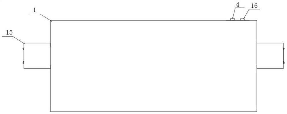
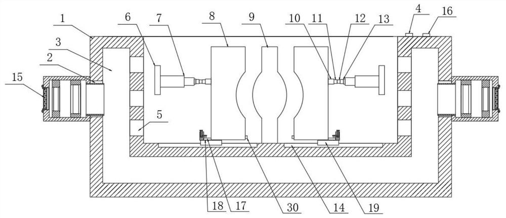
[0030] refer to Figure 1-2 And 4-6, a medical neurosurgical balloon injection molding device, including a mold body 1, positioning blocks 6 are fixedly arranged on both sides of the mold body 1, and an electric push rod 7 is fixedly installed on the inner side of the positioning block 6, and the electric push rod 7. A bearing 13 is fixedly installed at the telescopic end, and a small telescopic rod 12 is installed for rotation in the bearing 13. The telescopic end of the small telescopic rod 12 is fixedly connected with a screw rod 11. Connection, the bottom of the template 8 is provided with a slider 19, the template 8 is detachably mounted on the slider 19, the slider 19 is slidably set in the chute 14, the chute 14 is horizontally opened at the bottom of the mold body 1, and the bottom of the mold body 1 A positioning module 9 is fixedly arranged, and the positioning module 9 is arranged between the two templates 8. A gasket 30 is arranged on the inner side of the lower en...

Embodiment 2

[0037] refer to Figure 1-6 , a medical neurosurgery balloon injection molding device, comprising a mold body 1, positioning blocks 6 are fixedly arranged on both sides of the inside of the mold body 1, an electric push rod 7 is fixedly arranged on the inner side of the positioning block 6, and the telescopic end of the electric push rod 7 is fixed A bearing 13 is provided, and a small telescopic rod 12 is arranged to rotate inside the bearing 13. The telescoping end of the small telescopic rod 12 is fixedly connected with a screw 11, and the thread of the screw 11 is set in the sleeve 10. The sleeve 10 is fixedly connected with the template 8, and the template 8 The bottom is provided with a slider 19, the template 8 is detachably mounted on the slider 19, the slider 19 is slidably arranged in the chute 14, the chute 14 is set horizontally at the bottom of the mold body 1, and the inner bottom of the mold body 1 is fixedly provided with a positioning Module 9, the positioning...


PUM


Abstract

The invention discloses a medical neurosurgery balloon injection molding device which comprises a mold body, positioning blocks are fixedly arranged on the two sides in the mold body respectively, electric push rods are fixedly arranged on the inner sides of the positioning blocks, bearings are fixedly arranged at the telescopic ends of the electric push rods, small telescopic rods are rotationally arranged in the bearings, the telescopic end of the small telescopic rod is fixedly connected with a screw rod, the screw rod is sleeved with a sleeve in a threaded mode, the sleeve is fixedly connected with mold plates, sliding blocks are arranged at the bottoms of the mold plates, the mold plates are detachably installed on the sliding blocks, the sliding blocks are arranged in sliding grooves in a sliding mode, the sliding grooves are transversely formed in the inner bottom of the mold body, a positioning module is fixedly arranged at the bottom in the mold body, the positioning module is arranged between the two mold plates, a sealing gasket is arranged on the inner side of the lower end of each mold plate, and the cross section of each sealing gasket is arc-shaped. The injection molding device solves the problems that an existing injection molding device is inconvenient to demold, and a molded balloon is difficult to take down.

Description

technical field [0001] The invention relates to the field of medical technology, in particular to a medical neurosurgical balloon injection molding device. Background technique [0002] Medical balloons are used to administer a variety of treatments. For example, during angioplasty procedures, balloons may be used to widen constricted body blood vessels, such as coronary arteries. Balloons can also be used to deliver tubular members such as stents that are placed in the body to strengthen or reopen blocked blood vessels. In angioplasty, balloons can be used to treat stenosis, or narrowing, of blood vessels in the body by collapsing the balloon and delivering it to regions of the vessel that have been narrowed to the extent that blood flow is restricted. The balloon can be delivered to the target site by threading the catheter over a placed guide wire and advancing the catheter to the site. In some cases, the path to this site can be quite tortuous and / or narrow. After re...

Claims


Application Information

Patent Timeline
Patent Type & Authority Applications(China)
IPC IPC(8): A61M25/10
CPCA61M25/1029A61M25/104
Inventor 杨幸达邹志斌胡友珠俞大林邹国荣朱红罗庆勇钟波汤予云熊志强
Owner 新余市人民医院
Features
  • R&D
  • Intellectual Property
  • Life Sciences
  • Materials
  • Tech Scout
  • Unparalleled Data Quality
  • Higher Quality Content
  • 60% Fewer Hallucinations
Learn More