Purification mechanism, cooling machine and purification detection method

A technology of cooling machine and purification device, which is applied in chemical instruments and methods, separation methods, maintenance and safety accessories, etc., can solve problems such as easy pollution of cooling machines

Pending Publication Date: 2021-11-26
ZHUHAI GREE INTELLIGENT EQUIP CO LTD +1
View PDF17 Cites 0 Cited by
  • Summary
  • Abstract
  • Description
  • Claims
  • Application Information

AI Technical Summary

Problems solved by technology

[0005] The main purpose of the present invention is to provide a purification mechanism, a cooling machine and a purification detection method to solve the problem of easy pollution inside the cooling machine in the prior art

Method used


Image

  • Purification mechanism, cooling machine and purification detection method
  • Purification mechanism, cooling machine and purification detection method

Examples


Embodiment Construction

[0024] It should be noted that, in the case of no conflict, the embodiments in the present application and the features in the embodiments can be combined with each other. The present invention will be described in detail below with reference to the accompanying drawings and examples.

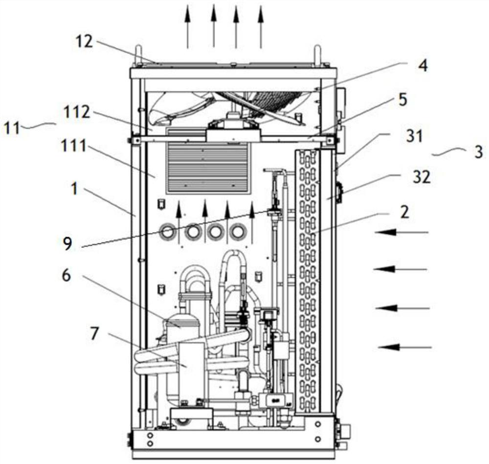
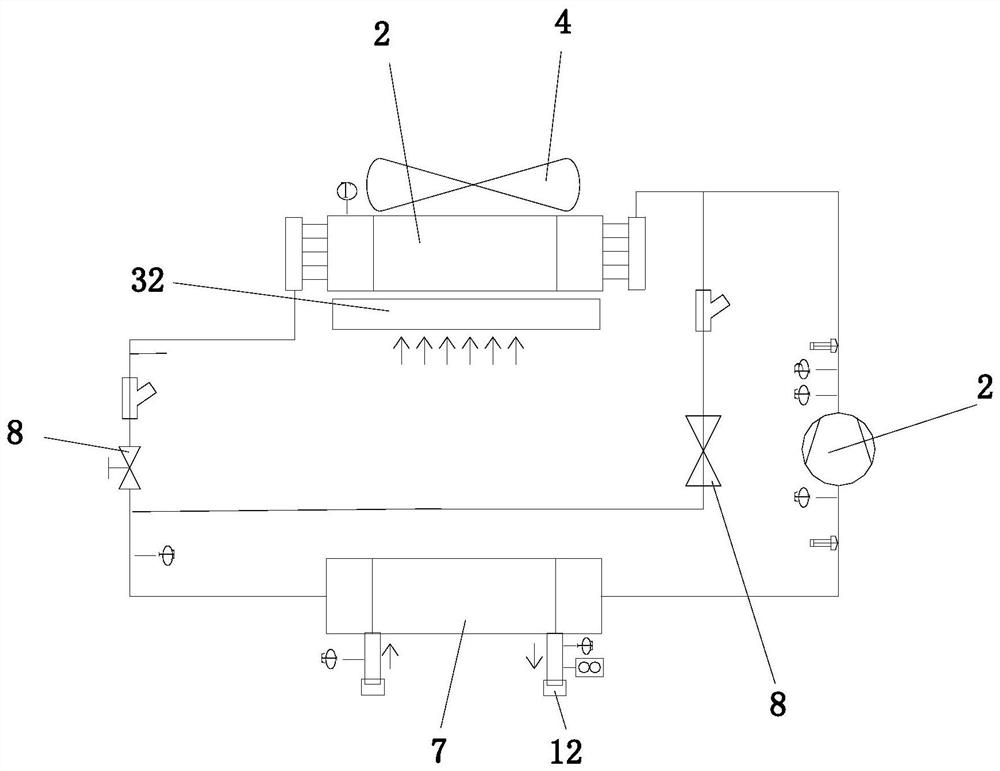
[0025] The purification mechanism of this embodiment, see figure 1 , figure 2 , used to purify the fluid in the cooling machine, the purification mechanism includes: a casing 1, the casing 1 has an accommodating cavity 11, and the casing 1 has a fluid inlet for the fluid outside the cooling machine to enter the accommodating cavity 11; the condenser 2. The condenser 2 is arranged on the casing 1; the purification device 3, the purification device 3 is used to purify the fluid flowing through the purification device 3; wherein, the purification device 3 is arranged on the side of the condenser 2 away from the accommodating cavity 11 , so that the fluid outside the accommodating cavity 11 ente...


PUM


Abstract

The invention provides a purification mechanism, a cooling machine and a purification detection method. The purification mechanism is used for purifying fluid in the cooling machine and comprises a machine shell, wherein the machine shell is provided with a containing cavity, and the machine shell is provided with a fluid inlet allowing fluid outside the cooling machine to enter the containing cavity; a condenser arranged on the machine shell; and a purification device used for purifying the fluid flowing through the purification device. The purification device is arranged on the side, away from the containing cavity, of the condenser, so that the fluid outside the containing cavity sequentially passes through the purification device and the condenser to enter the containing cavity. The purification mechanism solves the problem that in the prior art, pollution is likely to be generated in a cooling machine.

Description

technical field [0001] The invention relates to the field of coolers, in particular to a purification mechanism, a cooler and a purification detection method. Background technique [0002] Existing machine tool cooling machines are mainly used for cooling processing equipment such as numerical control machine tools, and are mainly used in indoor environments of factories. [0003] However, the higher-end and more precise machine tools have higher requirements on the environment, and have higher requirements on the temperature, humidity and cleanliness of the factory. Therefore, changes in ambient temperature will affect the workpiece, resulting in increased processing deviation. If the environment is dirty, some dust pollutants will be attached to the machine tool itself, resulting in a decrease in the accuracy of the machine tool itself. [0004] Moreover, the machine tool will also generate a lot of heat, chip residue, dust, waste, etc. during the processing. Need regul...

Claims


Application Information

Patent Timeline
IPC IPC(8): B23Q11/12B01D5/00B01D46/00B01D46/10
CPCB23Q11/126B01D46/10B01D46/0002B01D5/00
Inventor 董志华刘帅王涛叶润泽黄家峰
Owner ZHUHAI GREE INTELLIGENT EQUIP CO LTD
Why Eureka
Try Eureka