Vehicle braking/driving force control device

a technology of braking/driving force and control device, which is applied in the direction of electric devices, brake systems, instruments, etc., can solve the problems of reducing the control property of yaw rate or lateral acceleration that can occur in the vehicle, reducing the braking/driving force of the motor, and reducing the control property of the yaw rate or lateral acceleration. the effect of good stability of the vehicl

Inactive Publication Date: 2014-11-20
TOYOTA JIDOSHA KK
View PDF0 Cites 10 Cited by
  • Summary
  • Abstract
  • Description
  • Claims
  • Application Information

AI Technical Summary

Benefits of technology

[0028]The driving force or the braking force of the wheel or the braking force should be distributed depending on the load balance between the front wheel and the rear wheel to obtain the good stability of the vehicle. However, because the cooling performance of in-wheel motors of all wheels decreases at the low-speed traveling, a difference is easy to be produced in the thermal margin of the in-wheel motor by adjusting the depending on the load balance. Thus, in the present invention, the distribution adjustment means lowers the degree to adjust to the distribution depending on the load balance when the vehicle speed is low in comparison with the case of high speed condition of the vehicle. That is to say, the degree to adjust to the distribution depending on the thermal margin balance is big when the vehicle speed is low in comparison with the case of high speed condition of the vehicle. Therefore, according to the present invention, at the normal traveling, the good stability of the vehicle is provided and can average the temperature of the each in-wheel motor at the low-speed traveling. Note that, the wording of “to acquire the load balance” means acquiring information representing the load balance. The load balance may be acquired, for example, from the detection value of a load sensor provided to detect the load acting on each wheel, or it may be acquired from the calculation value with the detection value of a vehicle height sensor and a spring constant of the suspension, or it may the preset fixed value.

Problems solved by technology

However, in the driving force control device proposed to Patent Literature 1, the distribution change of the braking / driving force responded to the heat generation state of the motor is not performed at all in the period when it is not estimated that motor temperature will exceed the permission limit temperature, and the braking / driving force of the motor is limited at the point in time when it is estimated that the motor temperature will exceed the permission limit temperature.
Therefore, during the period until the point in time, a big difference occurs in the use situation of each motor, and the heat generation state of each motor becomes imbalance, and a motor with enough thermal margins is mixed with a motor with a little thermal margins.
Thus, because thermal margins of each motor may become imbalance, only one motor may reach the permission limit temperature at an early stage.
In this case, because the braking / driving force of the motor will be limited from the point in time, the control property of the yaw rate or the lateral acceleration that can occur in the vehicle may decrease.

Method used


Image

  • Vehicle braking/driving force control device
  • Vehicle braking/driving force control device
  • Vehicle braking/driving force control device

Examples


first embodiment

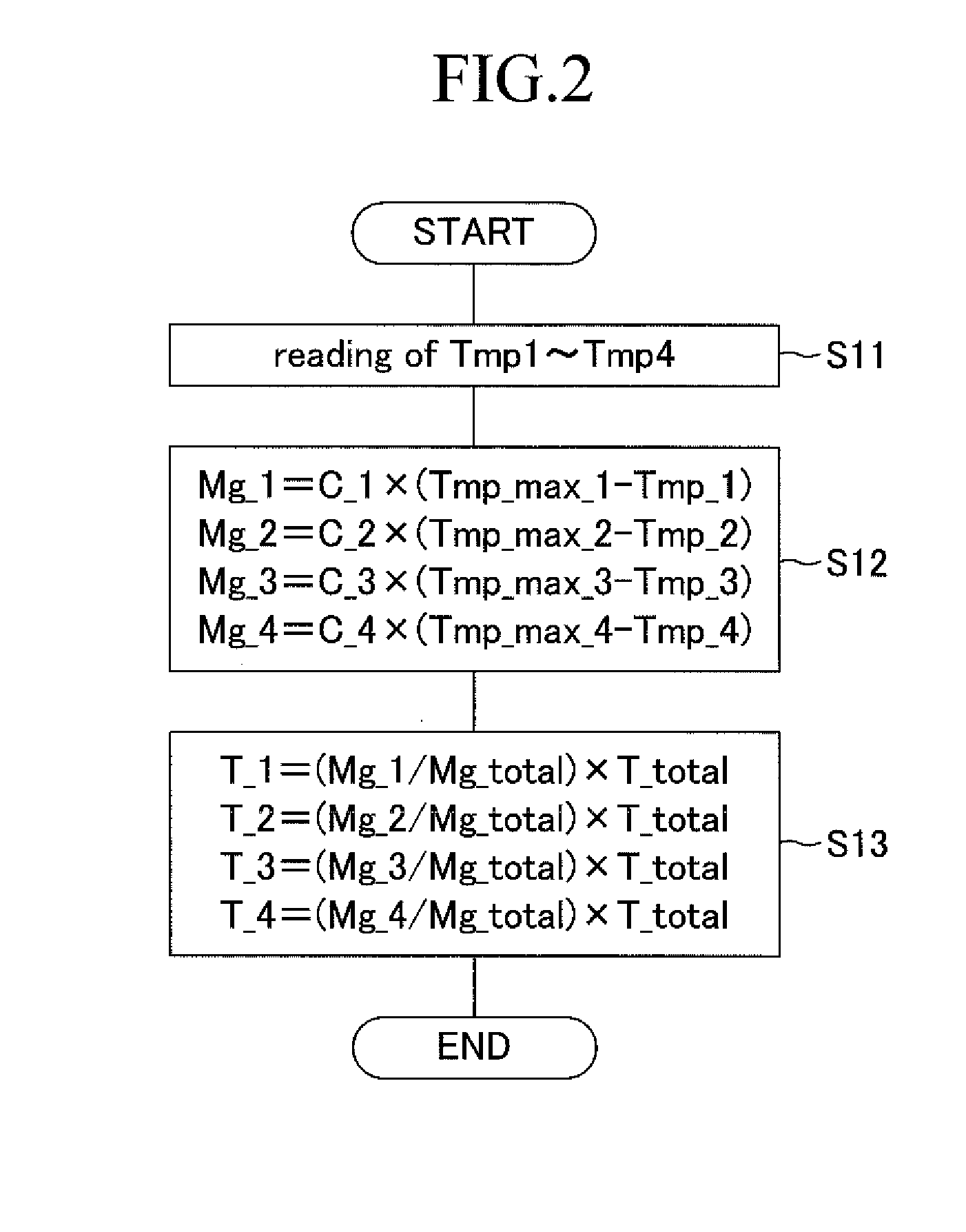
[0053]A method to divide the total requested braking / driving force into the requested braking / driving force for each wheel is described. FIG. 2 represents the braking / driving force distribution control routine performed by the ECU 40. The braking / driving force distribution control routine is performed repeatedly in a scheduled short period in the period when an ignition switch is turned on. Note that, about the braking / driving force distribution control routine, an embodiment here is referred to as a first embodiment because of describing a plurality of embodiments as follows.

[0054]When the braking / driving force distribution control routine of the first embodiment starts, in step S11, the ECU 40 reads motor temperatures Tmp_1, Tmp_2, Tmp_3, Tmp_4 detected by temperature sensors 50_1-50_4 provided with each in-wheel motor 20_1-20_4. Then subsequently, in step S12, thermal margins Mg_1, Mg_2, Mg_3, Mg_4 in-wheel motors 20_1-20_4 are calculated. In this embodiment, thermal margins Mg_1...

second embodiment

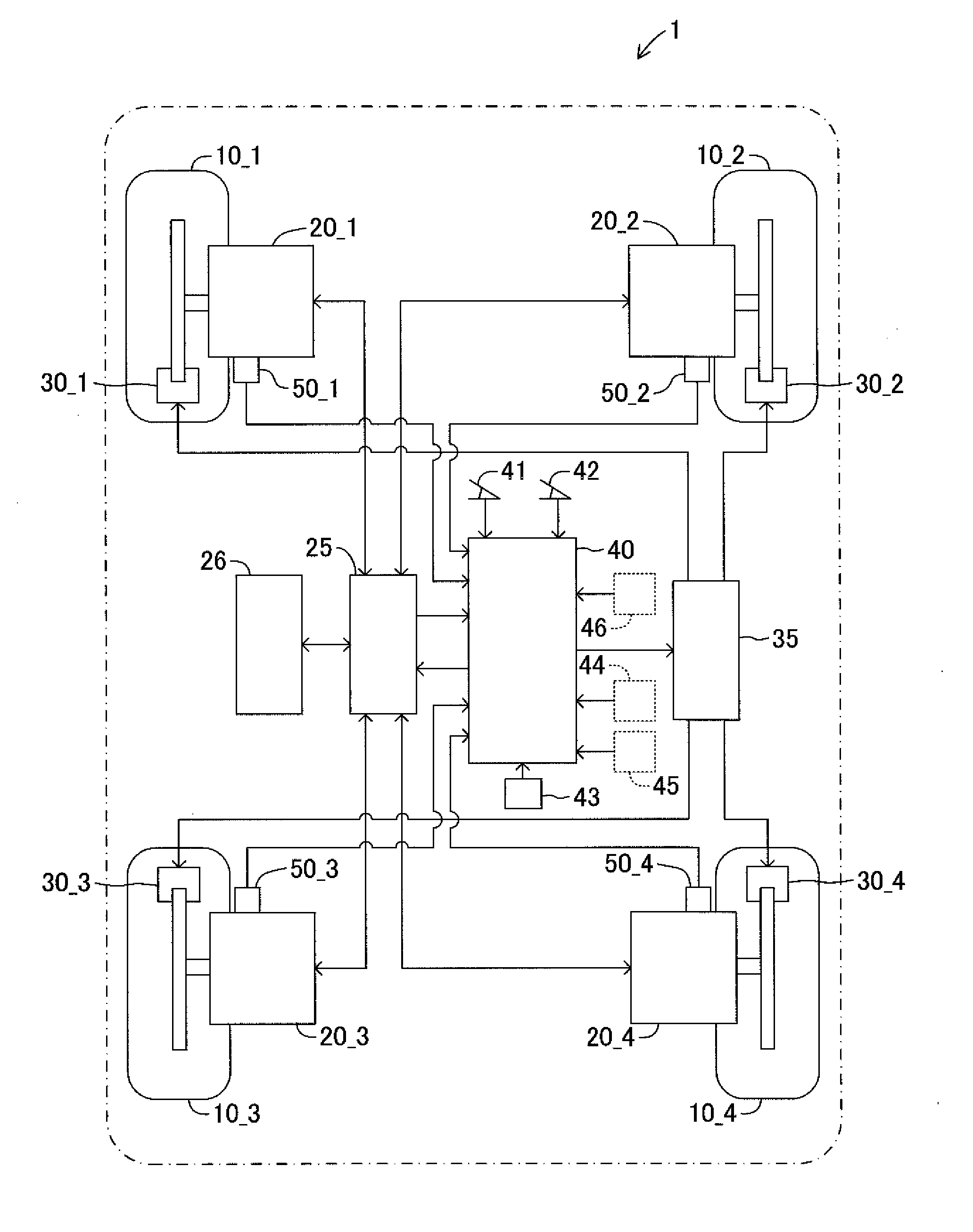
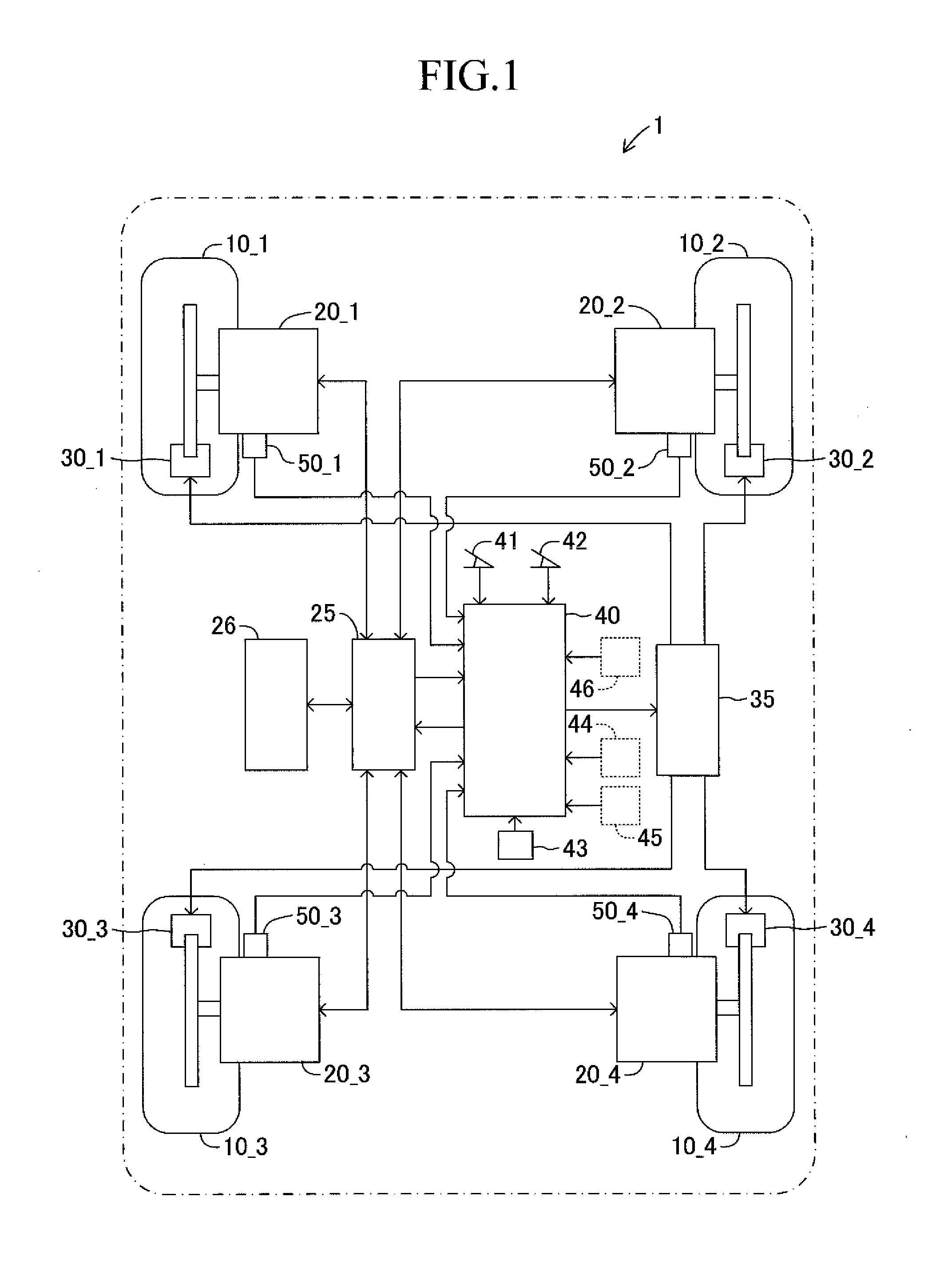
[0067]At high-speed traveling of the vehicle 1, the cooling performance of in-wheel motors 20 caused by the wind improves, but in-wheel motors 20_3, 20_4 of rear wheels 10_3, 10_4 are inferior to in-wheel motors 20_1, 20_2 of front wheels 10_1, 10_2 in cooling performance because of being hard to come in contact with the wind. Thus, in the second embodiment, the distribution of requested torque for each wheel is set to mainly use in-wheel motors 20_1, 20_2 of front wheels 10_1, 10_2 being easy to cool down at high-speed traveling of the vehicle 1, and the overheat of in-wheel motors 20_3, 20_4 of wheels 10_3, 10_4 is prevented.

[0068]FIG. 4 represents a braking / driving force distribution control routine performed by the ECU 40 as the second embodiment. In this the braking / driving force distribution control routine, the processing of step S12 of the first embodiment have been changed to steps S21, S22, S23, and other processing (S11, S13) is the same in the case of the first embodimen...

third embodiment

[0080]In the third embodiment, the vehicle 1 is provided with an acceleration sensor 45 to detect the load movement of the vehicle 1 in FIG. 1 as shown in broken line. The acceleration sensor 45 detects the acceleration G in the longitudinal direction of the vehicle 1 and outputs a sensor signal representing detected acceleration G in the ECU 40. The acceleration sensor 45 detects the acceleration in the longitudinal direction during acceleration and deceleration, and in addition, detects the acceleration in the longitudinal direction depending on the angle of the slope because a gravitational direction at the time of traveling on a downhill or an uphill relatively inclines to the longitudinal direction in comparison with at the time of horizontal traveling.

[0081]FIG. 6 represents a braking / driving force distribution control routine performed by the ECU 40 as the third embodiment. In this the braking / driving force distribution control routine, the processing of step S13 of the first...


PUM


Abstract

An ECU calculates the thermal margins of the in-wheel motors, on the basis of the thermal capacities of the in-wheel motors, the allowable limit temperatures, and the motor temperatures. Next, the ECU distributes the total requested torque between the requested torques for each wheel using the percentages of the thermal margins. The ECU controls the operation of an inverter such that the in-wheel motors generate the requested torques for the wheels. Thus, the four in-wheel motors generate uniform amounts of heat.

Description

TECHNICAL FIELD[0001]The present invention relates to a vehicle braking / driving force control device for controlling a driving force or a braking force to produce with each wheel of the vehicle individually.BACKGROUND ART[0002]As one form of electric cars, an in-wheel motor type vehicle in which a motor is arranged in or around the wheel placed under the vehicle body spring and drives the wheel directly is developed. In the in-wheel motor type vehicle, it is possible to control the driving force or the braking force given to each wheel independently depending on the traveling condition of the vehicle by an independent drive (power running) control or an independently regenerative control of a motor provided to every wheel.[0003]Because a motor is arranged in or around the wheel in such an in-wheel motor type vehicle, generated heat by the braking / driving movement of the motor is hard to be emitted and the motor is easy to be full of heat. Thus, for example, in the driving force cont...

Claims


Application Information

Patent Timeline
Patent Type & Authority Applications(United States)
IPC IPC(8): B60T7/12
CPCB60T7/12B60K7/0007B60L7/18B60W10/08B60W30/1843B60L2220/44B60L7/26B60L15/2009B60L2240/425B60T8/17552B60T2240/06B60L7/08B60L2240/36Y02T10/64Y02T10/72
Inventor ONODA, YUICHITAKAKUWA, KEIFUKUDOME, HIDEKITAKAHASHI, SATOSHI
Owner TOYOTA JIDOSHA KK
Why Eureka
Try Eureka