Membrane processing and positioning bracket for laminator

A technology for positioning brackets and laminators, applied in the application field of laminators, can solve the problems of reducing processing efficiency, difficult to achieve diaphragm positioning, laminator deviation, etc., to improve processing quality, reasonable and reliable structure, and avoid movement deviation. Effect

Pending Publication Date: 2021-11-26
绍兴市上虞龙马机电有限公司
View PDF7 Cites 0 Cited by
  • Summary
  • Abstract
  • Description
  • Claims
  • Application Information

AI Technical Summary

Problems solved by technology

[0003] In the patent document "CN103042688A A kind of film press", it can press two different films (high temperature resistant film and thermoformed film) on the same machine, which is convenient to process and low in cost, but the film is in the process of pressing , usually for direct transport, it is easy to deviate from the laminator, and it is difficult to realize the positioning of the diaphragm, resulting in inaccurate correspondence between the pressed lines and the diaphragm and affecting the processing quality. When the positioning bracket is used to press the diaphragm of the laminator, it is difficult Matching different types of film laminating machines will have a certain impact on the diaphragm transportation, and it is difficult to realize the rapid transportation of the diaphragm, which reduces the processing efficiency. At the same time, it is difficult to ensure the accurate positioning of the diaphragm, which brings inconvenience to the production and processing
At present, there is no diaphragm processing and positioning bracket for film laminators with reasonable and reliable structure, adjustment and conveying functions, and accurate positioning.

Method used


Image

  • Membrane processing and positioning bracket for laminator
  • Membrane processing and positioning bracket for laminator
  • Membrane processing and positioning bracket for laminator

Examples


Embodiment Construction

[0031] In order to enable those skilled in the art to better understand the solution of the present application, the technical solution in the embodiment of the application will be clearly and completely described below in conjunction with the accompanying drawings in the embodiment of the application. Obviously, the described embodiment is only It is an embodiment of a part of the application, but not all of the embodiments. Based on the embodiments in this application, all other embodiments obtained by persons of ordinary skill in the art without creative efforts shall fall within the scope of protection of this application.

[0032] It should be noted that the terms "first" and "second" in the description and claims of the present application and the above drawings are used to distinguish similar objects, but not necessarily used to describe a specific sequence or sequence. It should be understood that the data so used may be interchanged under appropriate circumstances for t...


PUM


Abstract

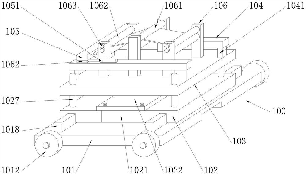
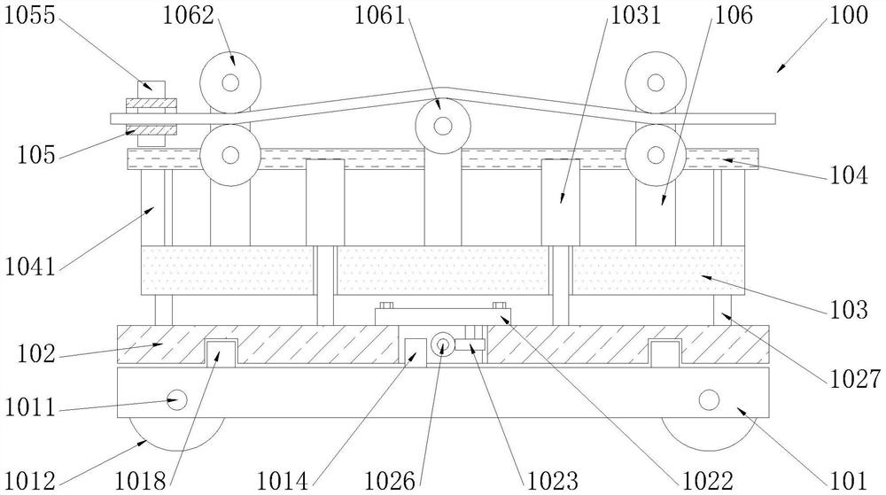
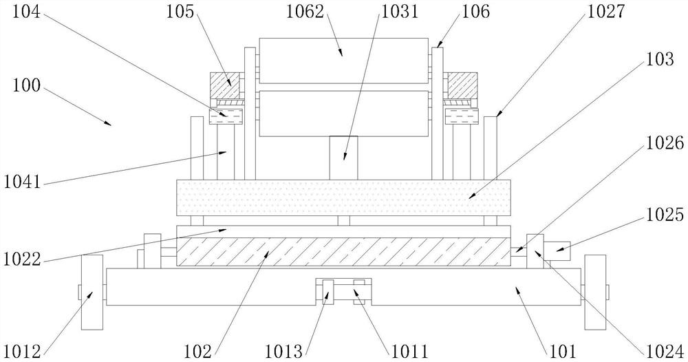
The invention discloses a membrane processing and positioning bracket for a laminator. The bracket comprises a bottom plate, a rotating shaft, rolling wheels, a limiting gear, a driving motor, a driving gear, a rack, a limiting plate, a guide rail, a groove, a sliding plate, a connecting plate, a cover plate, a transmission gear, a fixing base, an adjusting motor, a worm, a guide rod, a tooth groove, a cavity, a supporting plate, a hydraulic cylinder, a cross beam, a supporting rod, a moving plate, an air cylinder, a fixing plate, a positioning motor, a lead screw, an adjusting plate, a control switch, a sliding groove, an electric push rod, a pressing plate, a side plate, a guide roller, a press roller and a steering gear. The membrane processing and positioning bracket has the beneficial effects that the positioning bracket is adopted for conveying membranes, the positioning bracket has the functions of moving and height adjusting, the membranes can be rapidly conveyed, the membranes can be conveniently conveyed to the position of the laminator for processing and production of the membranes, the moving plate further has a limiting function and can conduct limiting treatment while the membranes are conveyed, the problem of movement deviation of the membranes during conveying is avoided, and accurate membrane positioning is guaranteed.

Description

technical field [0001] The invention relates to a diaphragm processing and positioning bracket for a laminator, in particular to a diaphragm processing and positioning bracket for a laminator, and belongs to the technical field of film laminating machines. Background technique [0002] Laminator is a special equipment used for lamination and forming of diaphragms. The lines on the diaphragm are generally passed by the film on the heated roller, and then pressed by the mold roller to form the required lines. There are textures engraved on the roller, and the texture is pressed on the diaphragm by the rotation of the roller. [0003] In the patent document "CN103042688A A kind of film press", it can press two different films (high temperature resistant film and thermoformed film) on the same machine, which is convenient to process and low in cost, but the film is in the process of pressing , usually for direct transport, it is easy to deviate from the laminator, and it is dif...

Claims


Application Information

Patent Timeline
Patent Type & Authority Applications(China)
IPC IPC(8): B29C65/60B29C65/78
CPCB29C65/60B29C65/7802B29C65/7858
Inventor 吴夏生吴新园
Owner 绍兴市上虞龙马机电有限公司
Why Eureka
Try Eureka