
Electromagnetic valve type urea solution injector

A technology of solenoid valves and injectors, which is applied in the direction of machines/engines, chemical instruments and methods, mechanical equipment, etc., can solve problems such as urea crystallization blocking nozzle holes, achieve the effects of lowering working temperature, improving heat dissipation effect, and improving reliability

Active Publication Date: 2012-11-14
LIUZHOU YUANCHUANG EFI TECH
View PDF0 Cites 4 Cited by
  • Summary
  • Abstract
  • Description
  • Claims
  • Application Information

AI Technical Summary

Problems solved by technology

[0004] The further technical problem to be solved by the present invention is: make the fuel injector able to solve the phenomenon of urea crystallization clogging the injection hole

Method used


Image

  • Electromagnetic valve type urea solution injector
  • Electromagnetic valve type urea solution injector
  • Electromagnetic valve type urea solution injector

Examples


Embodiment Construction

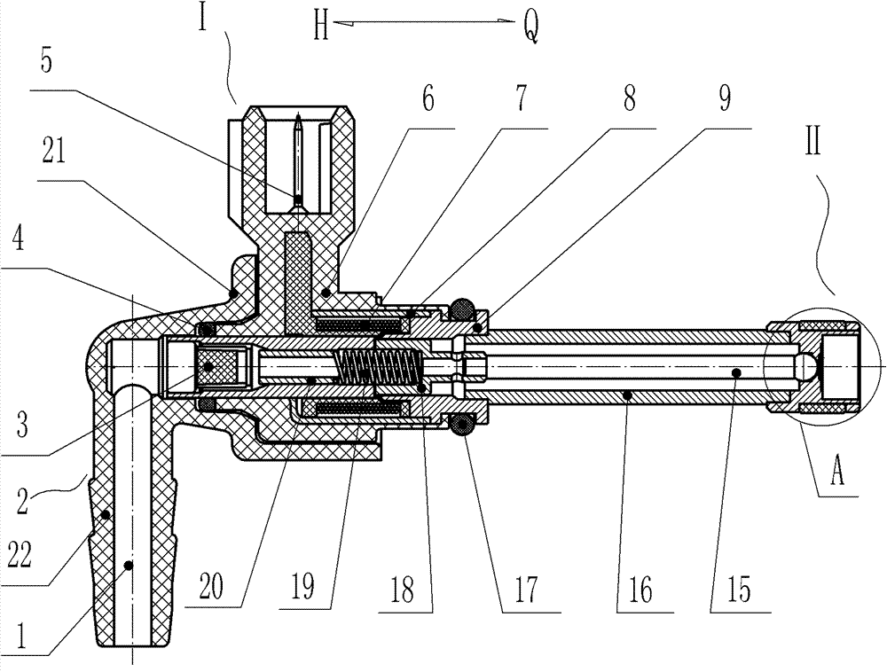
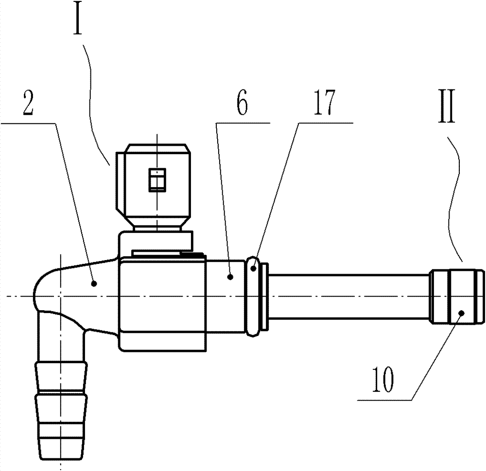
[0036] Such as figure 1 As shown, a solenoid valve injector for urea solution includes a solenoid valve injector I with a solution input port, a nozzle II with a spray hole, and the nozzle II is connected to the solenoid valve injector through a nozzle connecting rod 16. The spray body I is connected into one body to lengthen the length of the nozzle, increase the contact area between the nozzle and the cooling water, and enhance the cooling effect of the injector.

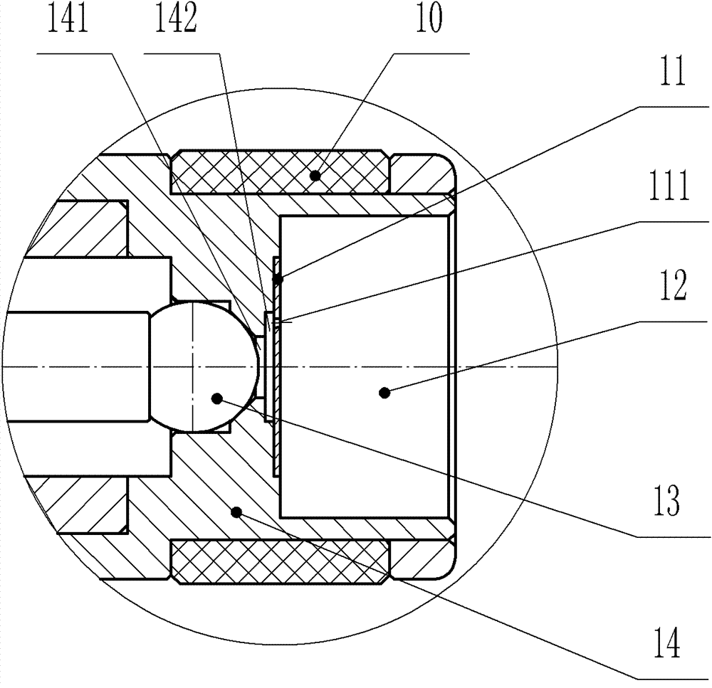
[0037] The nozzle II includes a valve seat 14 provided with a valve 141, a sealing steel ball 13 installed at the valve 141, an orifice plate 11 installed at the front end of the valve and having the spray hole 111 (see figure 2 ), and the valve seat 14 is provided with a step hole 12 forming a turbulent flow chamber A between the front end Q end and the nozzle plate 11; The thermal energy of the tail gas discharge pipe is introduced into the thermal insulation cover 10 of the nozzle; there is only one spray ho...


PUM


Abstract

An electromagnetic valve type urea solution injector relates to an injector, and comprises an electromagnetic valve type injecting body, and an injecting nozzle, wherein the electromagnetic valve type injecting body and the injecting nozzle are connected into a whole through an injecting nozzle connecting rod; the injecting nozzle comprises a valve seat, a sealing steel ball mounted at a valve, aspraying orifice plate provided with a spraying orifice and mounted at the front end of the valve, and a step hole is formed between the front end part of the valve seat and the spraying orifice plate to form a turbulent cavity A ; a heat-insulating sleeve is arranged on an excircle at the front end of the valve seat for preventing heat energy of a tail gas discharge pipe from passing into the injecting nozzle; and a single-orifice atomization structure is arranged in the injecting nozzle. The electromagnetic valve type urea solution injector can work in high-temperature and high-speed gas with long-term stability and very high reliability, has low possibility of blockage, and better solves the problem that the spraying orifice can be blocked up by urea crystals. The invention also has the advantages of low manufacturing cost, short maintenance time of the product, reasonable structure and convenience in installation, etc.

Description

technical field [0001] The invention relates to an injector, in particular to a urea solution electromagnetic valve injector used in a high-temperature and high-flow-velocity gas environment. Background technique [0002] One of the current treatment methods for diesel engine exhaust emissions is to use urea solution solenoid valve injector to directly spray urea solution into the exhaust pipe. Nitrogen is reduced to nitrogen gas and water. Because the nozzle of the urea solution electromagnetic valve injector is directly placed in the high temperature and high velocity gas above 600°C, it is easy to have urea crystallization to block the nozzle hole and deformation of the nozzle plate when it is used for a long time. Contents of the invention [0003] The main technical problem to be solved by the present invention is to provide a urea solution solenoid valve fuel injector so that the fuel injector can work stably for a long time in high temperature and high velocity gas...

Claims


Application Information

Patent Timeline
Patent Type & Authority Patents(China)
IPC IPC(8): F01N3/20B01D53/94
Inventor 唐凤君黎艺文
Owner LIUZHOU YUANCHUANG EFI TECH
Learn More