A curved variable cross-section flow channel type axial flow gas wave ejector

A technology of variable cross-section and ejector, which is applied in the direction of machines/engines, etc., can solve the problems that the gap between the nozzle and the drum cannot be monitored in real time, the flow loss of large gas injection and discharge, and the difficulty of adjusting the deflection angle between nozzles, etc., to achieve reduction The effect of equipment power consumption, reduction of gas incident and exhaust loss, and high energy utilization rate

Active Publication Date: 2022-07-26
DALIAN UNIV OF TECH
View PDF8 Cites 0 Cited by
  • Summary
  • Abstract
  • Description
  • Claims
  • Application Information

AI Technical Summary

Problems solved by technology

[0003] The compression-expansion unit mainly realizes energy transfer through the high-speed rotation of the turbine, which has poor liquid-carrying performance and high manufacturing and maintenance costs; the static ejector performs energy exchange through direct mixing of high and low pressure gases. Although the structure is simple, the energy transfer efficiency is low
[0004] The air wave ejector uses unsteady pressure waves to realize energy transfer. It has a simple structure, high efficiency and strong liquid carrying capacity, such as the patented axial flow jet air wave supercharger CN201220115597.0, etc., but there are Large gas incident and discharge flow loss, and the static pressure ratio of medium-pressure gas production is relatively low within a certain range of working conditions. In addition, it is difficult to adjust the deflection angle between nozzles, and the gap between nozzles and drums cannot be adjusted in real time. Monitoring and other issues

Method used


Image

  • A curved variable cross-section flow channel type axial flow gas wave ejector
  • A curved variable cross-section flow channel type axial flow gas wave ejector
  • A curved variable cross-section flow channel type axial flow gas wave ejector

Examples


Embodiment Construction

[0025] A typical implementation method of a curved variable cross-section flow channel type axial flow gas wave ejector of the present invention is described as follows, but is not limited to this implementation method.

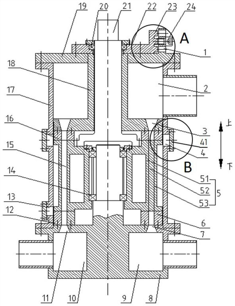
[0026] like figure 1 As shown in the figure, a curved variable-section flow channel type axial flow gas wave ejector of the present invention is mainly composed of a head 19, a transmission shaft 21, a declination adjustment plate 22, a drum 5, a low pressure nozzle 6, a base 8, a high pressure The nozzle 12 , the medium pressure nozzle 16 , the casing 17 and the support plate 18 are composed.

[0027] The casing 17 is a cylindrical structure, and the head 19 and the base 8 are respectively installed on both ends of the casing 17, so that a sealing structure is formed inside the casing 17; And the support plate 18 is located in the casing 17; the angle adjustment plate 22 is located outside the casing 17, and is fixed on the head (19);

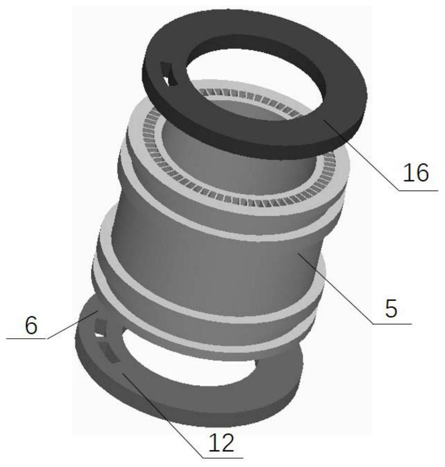
[0028] The drum 5 i...


PUM


Abstract

The invention relates to an axial-flow gas wave injector with a curved variable cross-section flow channel, belonging to the field of injecting and supercharging by means of gas jets. It is mainly composed of a shell, a main shaft, a base, a support plate, a shell, a declination adjustment plate, and a rotating drum composed of several curved and variable-section flow channels. The two ends of the flow channel form a certain angle with the axis of the drum, which can shorten the axial size of the drum, effectively reduce the incoming and outgoing losses of the airflow, and improve the energy transfer efficiency of pressure waves; The driving force of the airflow can reduce the power consumption of the equipment or output shaft power to the outside, and improve the overall efficiency of the equipment; the flow channel adopts the form of variable cross-section, which has the effect of strengthening expansion and recovering the dynamic pressure of the gas in the flow channel, making the equipment more powerful. The ejection capacity and static pressure conversion rate; the setting of the declination adjustment plate and the gap observation port help to simplify the operation and enhance the adjustability of the equipment.

Description

technical field [0001] The invention relates to an axial flow gas wave injector with a curved variable cross-section flow channel, which belongs to the field of injecting and supercharging by means of gas jets. Background technique [0002] Gas wave ejector is a new type of comprehensive utilization technology of pressure energy, which has important application value in many fields such as gas energy exploitation. At present, the devices used for ejection and boosting to achieve comprehensive utilization of pressure energy mainly include compression-expander units and static ejectors. [0003] The compression-expansion unit mainly realizes energy transfer through the high-speed rotation of the turbine, which has poor liquid-carrying performance and high manufacturing and maintenance costs. The static ejector performs energy exchange through direct mixing of high and low pressure gases. Although the structure is simple, the energy transfer efficiency is low. . [0004] The ...

Claims


Application Information

Patent Timeline
Patent Type & Authority Patents(China)
IPC IPC(8): F04F13/00
CPCF04F13/00
Inventor 胡大鹏赵一鸣刘凤霞于洋武锦涛李浩然
Owner DALIAN UNIV OF TECH
Why Eureka
Try Eureka