
Light path system of holographic aiming device with double-color switchable divided patterns

A technology of optical path system and aiming device, which is applied in the field of optical path system of holographic aiming device, and can solve problems such as single color and reticle pattern of holographic gun aiming, limited combat environment, etc.

Active Publication Date: 2021-11-26
三序光学科技(苏州)有限公司
View PDF4 Cites 0 Cited by
  • Summary
  • Abstract
  • Description
  • Claims
  • Application Information

AI Technical Summary

Problems solved by technology

[0006] The object of the present invention is to provide an optical path system of a holographic aiming device with two-color switchable reticle pattern, which uses different wavelength light sources and different holographic sheets to realize the holographic gun The color and pattern of the reticle can be switched in different combat scenarios to solve the above-mentioned problems of single color and reticle pattern of the holographic gun sight and limited combat environment

Method used


Image

  • Light path system of holographic aiming device with double-color switchable divided patterns
  • Light path system of holographic aiming device with double-color switchable divided patterns
  • Light path system of holographic aiming device with double-color switchable divided patterns

Examples


Embodiment 1

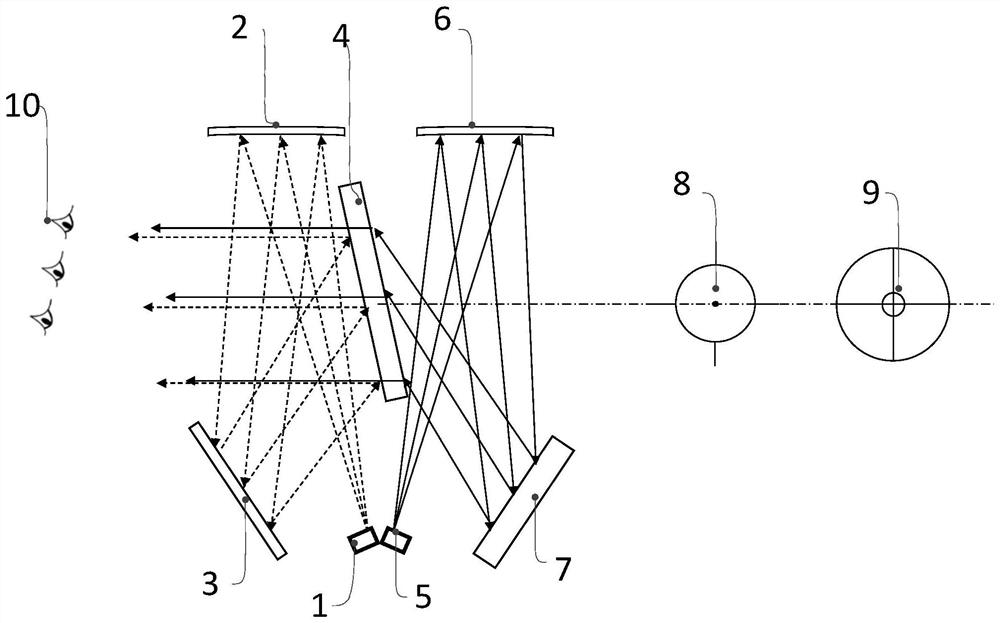
[0032] like figure 1 As shown, this embodiment provides an optical path system of a holographic aiming device with two-color multi-reticle patterns, the optical path system includes a first light source 1, a second light source 5, a first collimation device 2, and a second collimation device 6 , the first holographic sheet 3, the second holographic sheet 7, and the volume phase holographic grating 4.

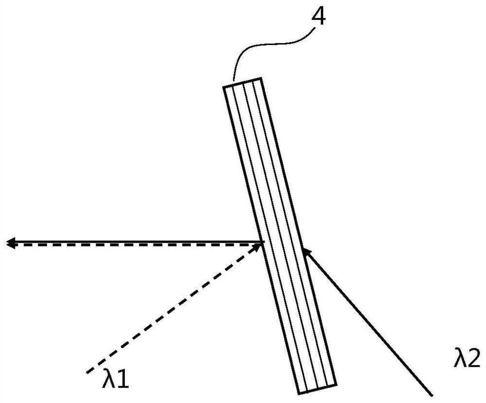
[0033] The light beam emitted by the first light source 1 passes through the first collimating device 2 and the first holographic sheet 3 in sequence, and then enters the first surface of the volume phase holographic grating 4 at an oblique angle and exits in parallel from the first surface, so the human eye 10 The restoration image 8 of the hologram recorded in the first hologram 3 can be seen through the second surface of the volume phase holographic grating 4; the light beam emitted by the second light source 5 passes through the second collimation device 6 in sequence, and t...

Embodiment 2

[0040] Embodiments 1 and 2 are mainly structurally different in the axial length of the bottom. For firearms with longer barrels, the bottom base of Embodiment 2 is a little longer. For pistols with short barrels, Embodiment 1 is suitable.

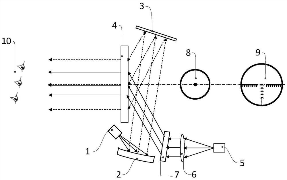
[0041] like image 3 As shown, this embodiment provides an optical path system of a holographic aiming device with two-color multi-reticle patterns, the optical path system includes a first light source 1, a second light source 5, a first collimation device 2, and a second collimation device 6 , the first holographic sheet 3, the second holographic sheet 7, and the volume phase holographic grating 4.

[0042] The light beam emitted by the first light source 1 passes through the first collimator 2 and the first hologram 3 in sequence, and then enters the second surface of the volume phase holographic grating 4 at an oblique angle and exits in parallel from the first surface, so the human eye 10 The restoration image 8 of the hologram recor...


PUM

PropertyMeasurementUnit
Wavelengthaaaaaaaaaa

Abstract

The invention relates to a light path system of a holographic aiming device with double-color switchable divided patterns. The light path system comprises a first light path system, a second light path system and a body position phase holographic grating; the first light path system is provided with a first light source, a first collimation device and a first holographic sheet; the second light path system is provided with a second light source, a second collimation device and a second holographic sheet; a light beam emitted by the first light source sequentially passes through the first collimation device and the first holographic sheet, then obliquely enters the body position phase holographic grating and then is emitted out in parallel; a light beam emitted by the second light source sequentially passes through the second collimation device and the second holographic sheet, then obliquely enters the body position phase holographic grating and then is emitted out in parallel. According to the system, the light sources with different wavelengths and different holographic sheets are utilized to realize switching use of divided colors and patterns of the holographic gun sight in different combat scenes, and the problems that the color and the divided pattern of the holographic gun sight are single and the combat environment is limited are solved.

Description

technical field [0001] The invention relates to an optical path system, in particular to an optical path system of a holographic aiming device with a two-color switchable reticle pattern. Background technique [0002] Since the 1990s, global urbanization has developed rapidly. Therefore, special forces in various countries and regions have begun to pay attention to the construction of close quarter battle capabilities (CBD, Close Quarter Battle). One of the characteristics of CQB is that warfighters will engage in uncertain, confined spaces. Before entering the combat environment, it is difficult for combat personnel to know the exact number and location of the opponent, and it is also impossible to determine the location of items in the environment, which brings great challenges to combat personnel. Facing the unknown environment, it can respond in time to the sudden appearance of the target. [0003] As we all know, traditional aiming devices such as mechanical sights an...

Claims


Application Information

Patent Timeline
IPC IPC(8): F41G1/00G03H1/00
CPCF41G1/00G03H1/0005
Inventor 朱兵兵董英琴
Owner 三序光学科技(苏州)有限公司
Learn More