Floating type thread gauge and automatic thread detection device using same

A detection device and thread thread technology, applied in the field of automatic thread detection devices, can solve the problems of non-replacement, low efficiency, and reduced detection efficiency, etc., and achieve the effects of rapid switching, improved efficiency, and rapid regulation or stoppage.

Pending Publication Date: 2021-11-26
昆山星益沅精密机械有限公司
View PDF12 Cites 1 Cited by
  • Summary
  • Abstract
  • Description
  • Claims
  • Application Information

AI Technical Summary

Problems solved by technology

[0002] In the current actual production of thread-related products, most of the thread inspections need to be manually inspected one by one or spot-checked by using thread go-gauge or stop-gauge, which is very inefficient.
Moreover, there are multiple threads of different calibers on related products, and it is necessary to continuously replace the thread go-gauge or stop-gauge according to the thread type during detection. According to the existing thread detection methods, it is often impossible to quickly perform different types of go-gauge or stop gauges. replacement, which reduces the detection efficiency

Method used


Image

  • Floating type thread gauge and automatic thread detection device using same
  • Floating type thread gauge and automatic thread detection device using same
  • Floating type thread gauge and automatic thread detection device using same

Examples


specific Embodiment 1

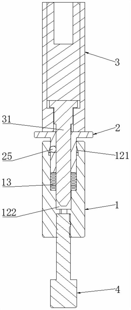
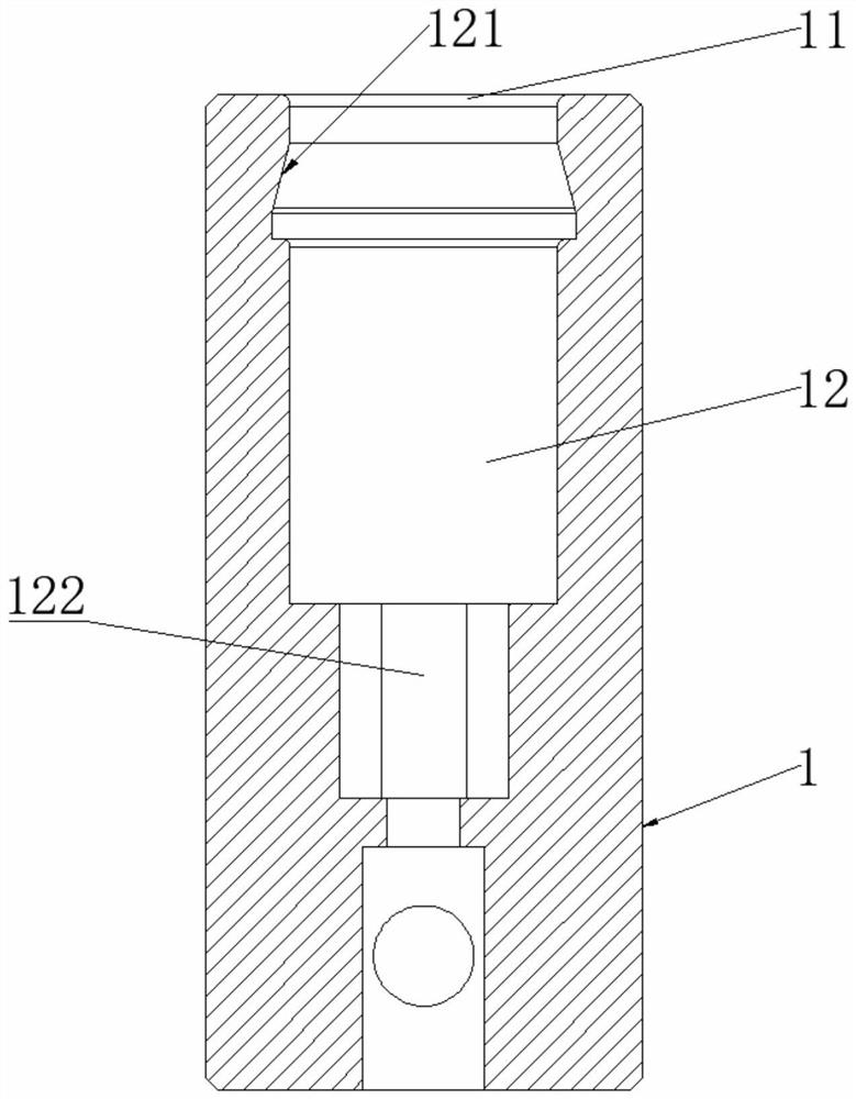
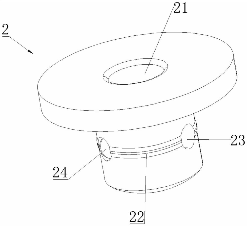
[0034] Such as figure 1 As shown, a floating thread gauge includes: a receiving part 1, a through gauge or a stop gauge 4 is installed at its lower end, the receiving part 1 has an inlet 11 arranged at the upper end and extends downward from the inlet 11 inside the receiving part 1 The channel 12 of the floating part 2, the middle position of which is configured as a through cavity 21 from top to bottom, the lower part of the floating part 2 is hidden in the receiving part 1 and limited in the channel 12, and the side wall of the lower part of the floating part 2 is provided with a movable Locking bead 24, a spring member 13 is set between the bottom end of floating part 2 and receiving part 1, so that floating part 2 can float up and down in a small range along the direction of channel 12; transfer part 3, an insertion part is installed at its lower end 31 , the insertion part 31 is inserted into the through cavity 21 from top to bottom, and is clamped in the through cavity 2...

specific Embodiment 2

[0044]Apply the above-mentioned floating thread gauge to an automatic thread detection device to realize automatic detection of threads, specifically, as Figure 4 with Figure 5 As shown, the automatic thread detection device includes:

[0045] A six-axis robot 5, the six-axis robot 5 has a reversible working head 51, and an adapter 3 is connected to the working head 51; the six-axis robot is a kind of humanoid operation, automatic control, reprogrammable, capable The mechatronics automatic production equipment that completes various operations in three-dimensional space can be used to control the movement of the adapter part, and can perform inspection work with high strength, high precision and high efficiency.

[0046] A base 6, arrange a plurality of receiving parts 1 in rows on the base 6, and each receiving part 1 has a corresponding floating part 2; They are all different, satisfying the thread test of different caliber threads on the product to be tested.

[0047] ...


PUM


Abstract

The invention discloses a floating type thread gauge and an automatic thread detection device using the same. The thread gauge comprises a bearing part, a floating part and a switching part; the bearing part is provided with an inlet disposed at the upper end and a channel extending downwards from the inlet in the bearing part; a through cavity from top to bottom is formed in the middle of the floating part, the lower portion of the floating part is hidden in the bearing part and limited in the channel, a movable locking ball is arranged on the side wall of the lower portion of the floating part, and a spring piece is arranged between the bottom end of the floating part and the bearing part so that the floating part can float up and down in the direction of the channel in a small range; and the lower end of the switching part is provided with an insertion part, the insertion part is inserted into the through cavity from top to bottom, and the insertion part is clamped in the through cavity by means of extrusion force which is generated by a locking ball in the radial direction and faces the center of the floating part. According to the thread gauge disclosed by the invention, the switching part, the floating part and the bearing part are matched with one another, so that the switching part and the floating part can be more conveniently and quickly dismounted and mounted, and the dismounting and mounting efficiency is improved.

Description

technical field [0001] The invention relates to the technical field of thread detection, in particular to a floating thread gauge and an automatic thread detection device using the thread gauge. Background technique [0002] In the actual production of thread-related products at present, most of the thread inspections need to be manually inspected one by one or spot-checked by using thread go-gauge or stop-gauge, and the efficiency is very low. Moreover, there are multiple threads of different calibers on related products, and it is necessary to continuously replace the thread go-gauge or stop-gauge according to the thread type during detection. According to the existing thread detection methods, it is often impossible to quickly perform different types of go-gauge or stop gauges. Replacement reduces the detection efficiency. Contents of the invention [0003] The technical problem to be solved by the present invention is to provide a floating thread gauge in view of the ...

Claims


Application Information

Patent Timeline
Patent Type & Authority Applications(China)
IPC IPC(8): G01B3/34
CPCG01B3/34
Inventor 况彬
Owner 昆山星益沅精密机械有限公司
Why Eureka
Try Eureka