Contact structure

A contact and moving contact technology, which is applied in the directions of contacts, circuit breaker contacts, electrical components, etc., can solve the problems of low rebound force and scattered holding force of moving contacts, and achieve stable and stable moving contacts. Concentrate and improve the effect of rebound strength

Pending Publication Date: 2021-11-26
诚硕电气有限公司
View PDF0 Cites 0 Cited by
  • Summary
  • Abstract
  • Description
  • Claims
  • Application Information

AI Technical Summary

Problems solved by technology

[0005] Aiming at the problems of low resilience and dispersed holding force of the existing movable contact, the present invention provides a contact structure, in which a circular first spring is installed inside the movable contact, and the first spring is used to generate deformation and apply force. Reaction force, improve the springback strength of the moving contact, the moving contact bracket is equipped with a contact shaft and a second spring, the end surface of the contact shaft is a slope structure, and the slope part is tangent to the limit part on the moving contact to realize the limit Bit abutment, so that the holding force of the moving contact is more concentrated, and the overall moving contact is more stable

Method used


Image

  • Contact structure
  • Contact structure
  • Contact structure

Examples


Embodiment Construction

[0024] The technical solutions of the present invention will be clearly and completely described below in conjunction with the embodiments. Obviously, the described embodiments are part of the embodiments of the present invention, but not all of them. Based on the embodiments of the present invention, all other embodiments obtained by persons of ordinary skill in the art without making creative efforts belong to the protection scope of the present invention.

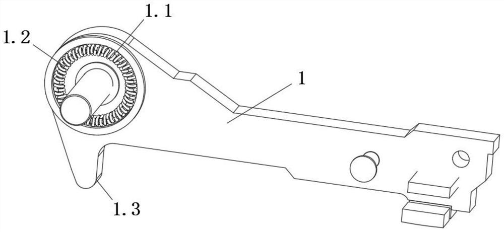
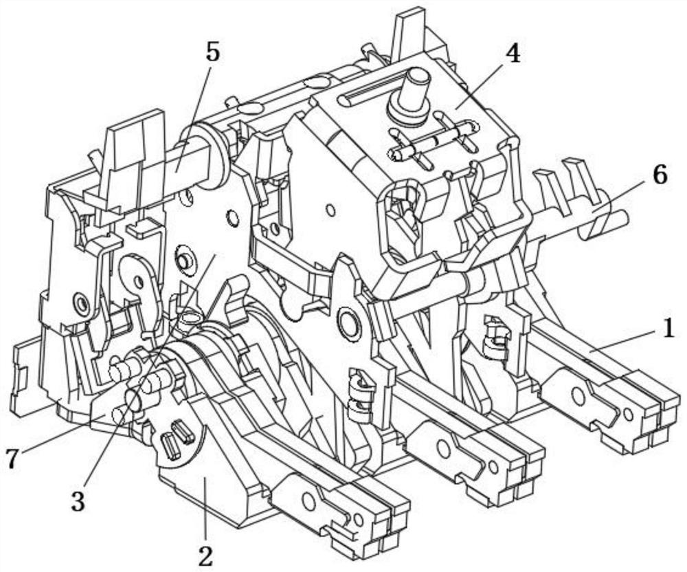
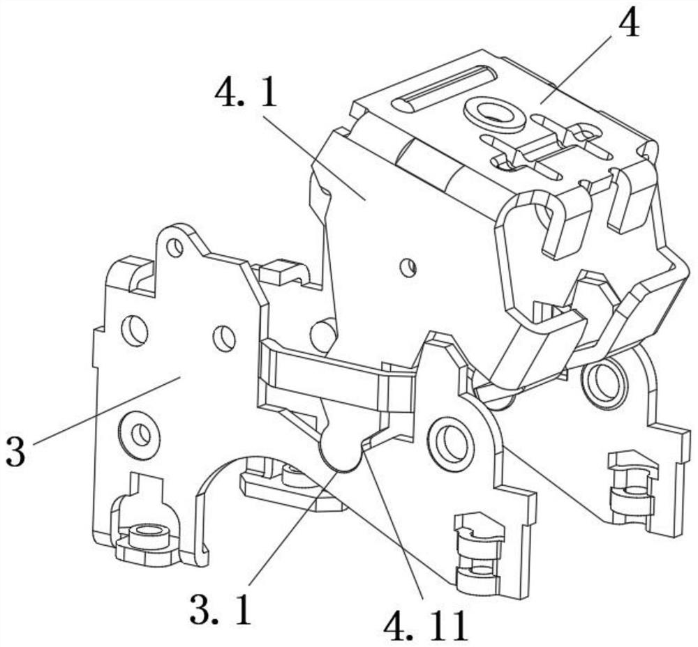
[0025] Such as Figure 1-6 As shown, it is a schematic structural diagram of a contact structure in a preferred embodiment of the present invention. This embodiment includes a moving contact 1 and a housing for accommodating the moving contact 1. The moving contact 1 There is a contact end abutting against the static contact and a non-contact end away from the static contact. The non-contact end has a cavity 1.1 for accommodating accessories. The first spring 1.2 is clamped in the cavity 1.1. The lower part of the non-c...


PUM


Abstract

The invention discloses a contact structure, and belongs to the technical field of electrical equipment, the contact structure comprises a moving contact and a shell used for accommodating the moving contact, the moving contact is provided with a contact end abutted against a static contact and a non-contact end far away from the static contact, the non-contact end is provided with a cavity used for accommodating accessories, and a first spring is clamped in the cavity. The lower portion of the non-contact end of the moving contact extends to be provided with a limiting portion, moving contact supports are arranged on the two sides of the moving contact, a contact shaft and a second spring are assembled in the moving contact supports, the axial surface of the contact shaft is inclined and tangent to the limiting portion, and a round first spring is assembled in the moving contact. The first spring is used for applying a counter-acting force after the first spring deforms, the rebound strength of the moving contact is improved, the contact shaft and the second spring are assembled in the moving contact support, the end face of the contact shaft is of an inclined face structure, and the inclined face part is tangent to the limiting part to achieve abutting connection, so that the retaining force of the moving contact is more concentrated, and the whole moving contact is more stable.

Description

technical field [0001] The invention belongs to the technical field of electrical equipment, and in particular relates to a contact structure. Background technique [0002] The moving contact is an important part of the circuit breaker and is used to make or break the current. When a short-circuit fault current occurs in the circuit, the circuit breaker drives the operating mechanism to quickly disconnect the dynamic and static contacts. At this time, the voltage between the dynamic and static contacts causes the air medium to discharge and generate an arc. During the combustion process, the arc expands the volume of the air at the contact, the temperature rises sharply, and the ionization accelerates. At the same time, the surface of the contact and nearby metal parts melts and evaporates due to high temperature, thus forming high-temperature and high-pressure gas inside the circuit breaker. [0003] The existing contact structure also has the following defects in use. ...

Claims


Application Information

Patent Timeline
Patent Type & Authority Applications(China)
IPC IPC(8): H01H73/04H01H1/50
CPCH01H73/04H01H1/50
Inventor 赵坤刘艳辉边玉兴
Owner 诚硕电气有限公司
Why Eureka
Try Eureka