
Eureka
For R&D, Eureka makes reading and utilizing patents & technical documents easy.
Eureka AIR
Designed for self-driven R&D workflows. Generate viable solutions, solve complex R&D challenges, empower your innovation with AI.

Eureka Materials
Designed for material experts only. Revolutionize your material R&D, from search, analyze, to developing new materials.

TechResearch
Generate reliable direction feasibility study reports for your R&D in just a few steps.

TechSeek
Discover and master advanced knowledge NOW. Basics, ideas, possibilities, all at once.

TechMind
As an expert in R&D Theories, TechMind can generates customized viable solutions instantly.

TechRisk
Analyze your overall solution with one click, know your potential R&D risks in advance.

TechMonitor
Get weekly tech updates, stay abreast of the latest tech innovations and key insights.
Wire pressing cap mounting device
A technology for installing devices and crimping caps, which is applied to the assembly/disassembly of connecting end caps and contact pieces, can solve the problems of high labor intensity, laborious pressing of crimping caps, high error rate, etc. Addresses easily broken effects
- Summary
- Abstract
- Description
- Claims
- Application Information
AI Technical Summary
Problems solved by technology
Method used
Image

Examples
Embodiment 1
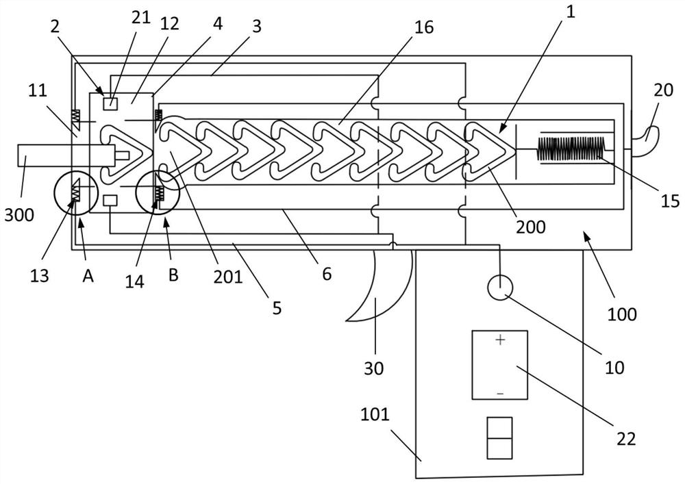
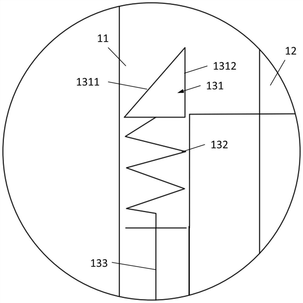
[0040] Such as figure 1 As shown, the present embodiment provides a wire crimping cap installation device, the device includes a body 100 , the body 100 is provided with a guide hole 1 , and the guide hole 1 is used for loading the crimping cap 200 . The crimping cap 200 is provided with a card interface 201, the guide hole 1 is provided with an installation port 11, and the card interface 201 and the installation port 11 are set in the same direction, so that the end of the wiring 300 can pass through the installation port 11 and be placed in the card interface Inside 201.
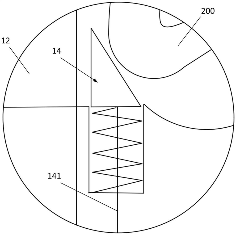
[0041] The body 100 is also provided with a heating module 2 and a clamping mechanism 3. The end of the guide hole 1 close to the installation port 11 is provided with a working position 12. The heating module 2 is arranged in the working position 12. The heating module 2 is configured to heat the crimping wire. The cap 200 is used to connect the crimping cap 200 and the wiring 300 to be connected. Comp...
Embodiment 2
[0068] Such as Figure 5 As shown, the difference between this embodiment and the first embodiment is that the second transmission assembly 6 that realizes the connection between the second control rod 142 and the second control switch 20 is a mechanical structure. The second transmission assembly 6 includes a cam 61 fixedly connected with the second control switch 20, the second control switch 20 and the cam 61 can rotate around the camshaft 601 together, the second transmission assembly 6 also includes a link spring 62, a buckle link 63, wherein the middle of the buckle link 63 is connected with the fixed shaft 602, and the buckle link 63 can rotate around the fixed shaft 602. At the initial position, the snap link 63 compresses the link spring 62 , and under the action of the thrust of the link spring 62 , one end abuts against the cam 61 , and the other end of the snap link 63 is hinged to the second control rod 142 .
[0069] When an external force acts on the second con...
PUM
 Abstract
Description
Claims
Application Information
 - R&D Engineer
- R&D Manager
- IP Professional
- Industry Leading Data Capabilities
- Powerful AI technology
- Patent DNA Extraction
Browse by: Latest US Patents, China's latest patents, Technical Efficacy Thesaurus, Application Domain, Technology Topic, Popular Technical Reports.
© 2024 PatSnap. All rights reserved.Legal|Privacy policy|Modern Slavery Act Transparency Statement|Sitemap|About US| Contact US: help@patsnap.com