Adjusting type guide rail for electrical installation and bending device thereof

A technology for electrical installation and bending devices, applied in cleaning methods and tools, cleaning methods using tools, chemical instruments and methods, etc., can solve the problem of inability to conveniently observe the values ​​of electrical components, affect the normal production of guide rails, and the positioning of sheets Inaccurate and other problems, to achieve the effect of improving the appearance, safe and convenient use, and preventing scratches

Active Publication Date: 2021-11-30
山东博物馆山东省文物鉴定中心
View PDF7 Cites 0 Cited by
  • Summary
  • Abstract
  • Description
  • Claims
  • Application Information

AI Technical Summary

Problems solved by technology

[0004] The present invention provides an adjustable guide rail for electrical installation and its bending device, which can effectively solve the problem that the guide rail proposed in the above background technology cannot be used during the installation process of electrical components due to the lack of a corresponding tilt angle adjustment mechanism. Install according to the inclination angle at the installation position. When the installation position of the electrical component is too low or too high, the value on the electrical component cannot be easily observed during the use of the electrical component. At the same time, during the bending process of the guide rail, In order to ensure the convenience of bending, the bending is often carried out directly through the whole sheet. When the sheet is loaded by pushing, it is easy to cause the bending of the sheet, resulting in inaccurate positioning of the sheet and affecting the positioning of the guide rail. Problems with normal production

Method used


Image

  • Adjusting type guide rail for electrical installation and bending device thereof
  • Adjusting type guide rail for electrical installation and bending device thereof
  • Adjusting type guide rail for electrical installation and bending device thereof

Examples


Embodiment

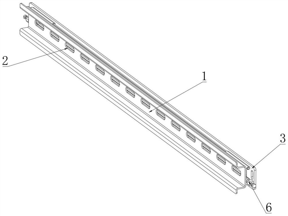
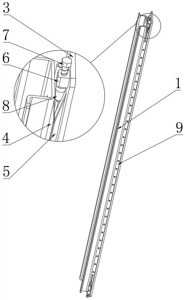
[0048] Example: such as Figure 1-2 As shown, the present invention provides a technical solution, an adjustable guide rail for electrical installation, including a guide rail main body 1, the middle part of the inside of the guide rail main body 1 is uniformly opened with a long installation hole 2, and the top of the back of the guide rail main body 1 is rotated through a shaft. The base plate 3, the driving inclined block 4 is bonded to the bottom of the back of the guide rail main body 1, the limit inclined block 5 is bonded to the bottom of the front of the mounting base plate 3, and the bottom of both ends of the front of the mounting base plate 3 is fixedly connected to the mounting small block 6, and the inner middle of the mounting small block 6 The driving bolt 7 is connected by thread, and the end of the driving bolt 7 is fixedly connected with the driving cone block 8 at the position between the driving slant block 4 and the limit slanting block 5. Limiting rubber ...


PUM


Abstract

The invention discloses an adjusting type guide rail for electrical installation. The adjusting type guide rail is characterized in that long mounting holes are uniformly formed in the middle of the inner side of a guide rail main body in a penetrating manner, the top of the back surface of the guide rail main body is rotatably connected with a mounting substrate through a rotating shaft, a driving inclined block is adhered to the bottom of the back surface of the guide rail main body, and a limiting inclined block is adhered to the bottom of the front surface of the mounting substrate; and small mounting blocks are fixedly connected to the bottoms of the two ends of the front face of the mounting substrate, driving bolts are connected to the middles of the inner sides of the small mounting blocks through threads, and driving conical blocks are fixedly connected to the positions, corresponding to the position between the driving inclined block and the limiting inclined block, of the ends of the driving bolts. According to the guide rail, the inclined angle of the guide rail main body is adjusted, the inclination angle of installed electrical elements is adjusted, so that the electrical elements at the too low position are inclined upwards, the electrical elements at the too high position are inclined upwards, and a user can observe data on the electrical elements more conveniently in the using process.

Description

technical field [0001] The invention relates to the technical field of electrical installation, in particular to an adjustable guide rail for electrical installation and a bending device thereof. Background technique [0002] DIN guide rail is a German industrial standard. The use of guide rail is an installation method for industrial electrical components. The electrical components that support this standard can be easily stuck on the guide rail without fixing with screws, and the maintenance is also very convenient. At the same time, it is installed on the guide rail. A bending device is required in the production process; [0003] However, during the use of the guide rail at present, due to the lack of a corresponding inclination angle adjustment mechanism, the electrical components can only be installed according to the inclination angle at the installation position during the installation process. When the installation position of the electrical components is too low or...

Claims


Application Information

Patent Timeline
IPC IPC(8): B21D11/22B21D11/00B08B1/04B08B1/00
CPCB21D11/22B21D11/00B08B1/12B08B1/32Y02P40/57
Inventor 李彬
Owner 山东博物馆山东省文物鉴定中心
Why Eureka
Try Eureka