Apparatus and method for additive manufacturing

A technology of additive manufacturing and powder silo, applied in the directions of additive manufacturing, additive processing, process efficiency improvement, etc., can solve the problems of high residual stress of laser-printed parts, complex performance at welded joints, and unfavorable forming of brittle materials, etc. Achieve the effect of avoiding the risk of deformation and cracking, improving applicability and printing quality, and optimizing powder particle size distribution

Active Publication Date: 2022-04-08
西安赛隆增材技术股份有限公司
View PDF14 Cites 0 Cited by
  • Summary
  • Abstract
  • Description
  • Claims
  • Application Information

AI Technical Summary

Problems solved by technology

[0003] The existing bi-metal / multi-metal processing technologies include the existing explosive composite technology, rolling composite method, powder metallurgy method, etc. First of all, due to the complexity of the processing method, the processing technology is relatively cumbersome, the production efficiency is low, and the cost is high. ; Second, most of the methods cannot directly shape the product parts, and it is necessary to realize the forming of the overall structural parts by welding. During welding, the performance of the welded joints is complicated due to the difference in materials; thirdly, it is easy to make bimetallic or multi- The metal bonding interface becomes the weakest point of the whole material or structure
The existing laser selective melting technology, because the energy source is laser, is difficult to form refractory metal materials, and for some structural parts with better performance, refractory metals are often used as the second metal, and at the same time, the residual stress of laser printing parts is more , which is not conducive to forming brittle materials, and because the difference in linear expansion coefficient between bimetals may be very large, it is more likely to cause stress concentration, which will lead to poor quality of structural parts and affect product yield

Method used


Image

  • Apparatus and method for additive manufacturing
  • Apparatus and method for additive manufacturing
  • Apparatus and method for additive manufacturing

Examples


Embodiment Construction

[0035] Example embodiments will now be described more fully with reference to the accompanying drawings. Example embodiments may, however, be embodied in many forms and should not be construed as limited to the examples set forth herein; rather, these embodiments are provided so that this disclosure will be thorough and complete and will fully convey the concept of example embodiments to those skilled in the art. The described features, structures, or characteristics may be combined in any suitable manner in one or more embodiments.

[0036] Furthermore, the drawings are merely schematic illustrations of embodiments of the disclosure and are not necessarily drawn to scale. The same reference numerals in the drawings denote the same or similar parts, and thus repeated descriptions thereof will be omitted. Some of the block diagrams shown in the drawings are functional entities and do not necessarily correspond to physically or logically separate entities.

[0037] In this ex...


PUM

PropertyMeasurementUnit
thicknessaaaaaaaaaa
thicknessaaaaaaaaaa

Abstract

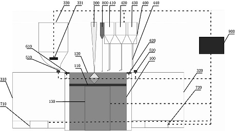
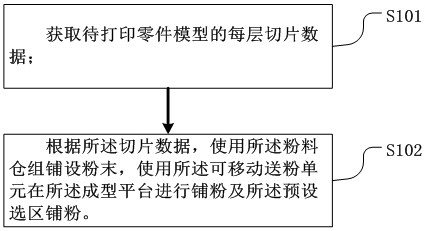
Embodiments of the present disclosure relate to an additive manufacturing device and method, including a forming chamber, a forming substrate, an electron beam heat source, a powder chamber group, a movable powder feeding unit, and a control unit. Due to the high-vacuum and clean environment, the invention reduces the impurity content in the printed parts, prevents the deterioration of the brittleness problem caused by the high impurity concentration, and adopts multiple powder bins and movable powder feeding units to solve the problem of bimetal or multi-metal Difficult puzzles. At the same time, bimetal components with complex shapes can be directly formed without subsequent machining and heat treatment, which improves the utilization rate of materials. Compared with traditional processing techniques, it greatly shortens the manufacturing cycle and saves costs. Moreover, multiple multi-layer scanning methods are adopted at the melting bonding interface, which is beneficial to increase the bonding strength of the bonding point.

Description

technical field [0001] Embodiments of the present disclosure relate to the technical field of metal additive manufacturing, and in particular, to an additive manufacturing device and method. Background technique [0002] Bi-metal / multi-metal composite materials are composed of two or more layers of metal alloys. Due to the combination of the advantages of two or more metals, they have a wide range of usability and process performance. Because of their special structure and properties, It can replace expensive materials or scarce metals in actual production. Nowadays, many bimetallic materials have been put into production, such as steel plates, steel bars, steel wires, steel pipes, etc. In the selection of metal materials, the main stress-bearing components are generally composed of thicker metals. In order to save costs, the main stress-bearing base materials will choose cheaper metals. According to the demand for bimetallic materials / multi-metallic materials, different c...

Claims


Application Information

Patent Timeline
Patent Type & Authority Patents(China)
IPC IPC(8): B22F12/30B22F12/41B22F12/52B22F12/90B22F10/28B22F10/85B22F10/366B33Y10/00B33Y30/00B33Y50/02
CPCB22F12/30B22F12/41B22F12/52B22F12/90B22F10/28B22F10/85B22F10/366B33Y10/00B33Y30/00B33Y50/02Y02P10/25
Inventor 程康康朱纪磊李会霞车倩颖王宇贺卫卫向长淑
Owner 西安赛隆增材技术股份有限公司
Why Eureka
Try Eureka