Trundle capable of being automatically folded and unfolded and electric control cart
An automatic retractable and caster technology, applied in the direction of casters, wheels, vehicle parts, etc., can solve the problems of difficulty in realizing retractable and retractable functions, stuck shafts and guide grooves, insufficient load-bearing capacity, etc. Caton, excellent bearing capacity
- Summary
- Abstract
- Description
- Claims
- Application Information
AI Technical Summary
Problems solved by technology
Method used
Image
Examples
Embodiment 1
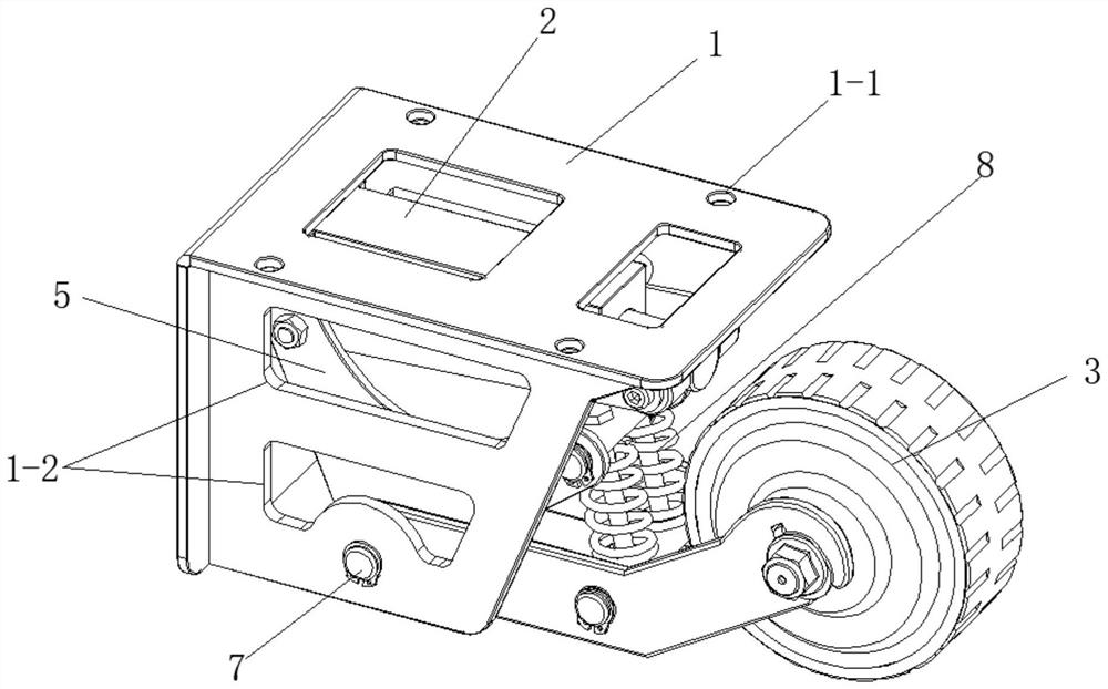
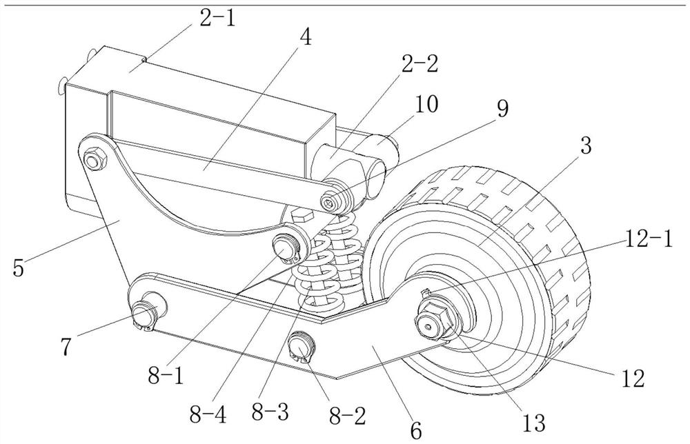
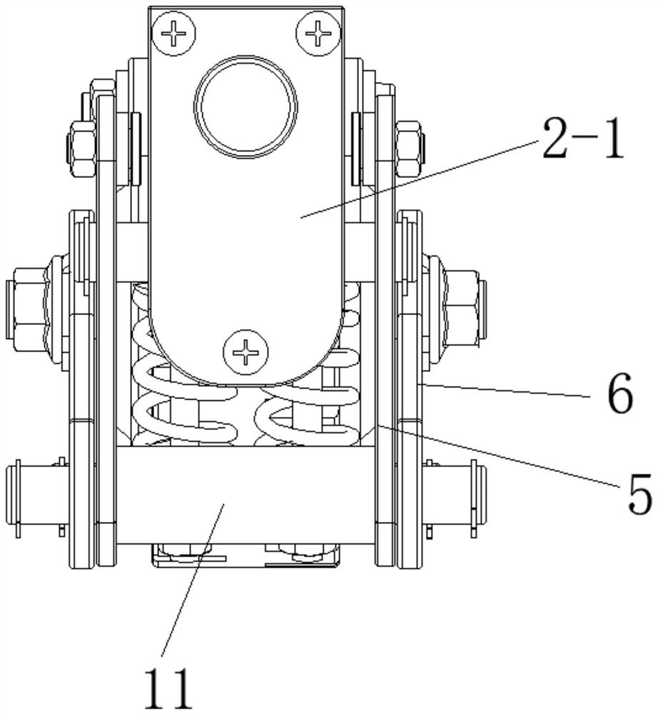
[0039] Such as Figure 1 to Figure 5 The electronically controlled cart shown includes a car body, a remote control panel, and casters located at the bottom of the car body. A power module and a controller electrically connected to the caster wheels are fixedly installed on the car body, and the remote control panel is wirelessly connected to the controller. The caster of this embodiment is an automatically retractable caster, including a fixed seat 1, a drive mechanism 2 fixedly installed in the fixed seat 1 and a transmission mechanism rotatably installed in the fixed seat 1, one end of the transmission mechanism and the output of the drive mechanism 2 The shafts are fixed and connected, and the other end is rotated with a wheel 3 with a hub motor. Use the remote control panel to control the movement of the caster, drive the transmission mechanism through the drive mechanism 2 to drive the wheel 3 to move down and reset, and use the hub motor to control the rotation and stop ...
Embodiment 2
[0051] The structure of this embodiment is similar to Embodiment 1, the difference is that the structure of the transmission mechanism is different, such as Figure 6 to Figure 7 As shown, Wheel 3 uses a three-inch brushless hub motor. The transmission mechanism includes a transmission assembly symmetrically arranged on both sides of the main body of the electric push rod. The transmission assembly includes a gas spring 23 and a second connecting rod 24 connected in rotation. The right end of the second connecting rod 24 is connected to the wheel 3 in rotation, and the middle part is connected to the fixed seat 1 The side wall rotation connection. Push the gas spring 23 through the electric push rod, and use the gas spring 23 to pull the second connecting rod 24 to rotate clockwise, thereby realizing the downward movement of the wheel 3. The structure is simpler, the production cost is low, and different usage requirements are met.
PUM
 Abstract
Description
Claims
Application Information
 - R&D
- Intellectual Property
- Life Sciences
- Materials
- Tech Scout
- Unparalleled Data Quality
- Higher Quality Content
- 60% Fewer Hallucinations
Browse by: Latest US Patents, China's latest patents, Technical Efficacy Thesaurus, Application Domain, Technology Topic, Popular Technical Reports.
© 2025 PatSnap. All rights reserved.Legal|Privacy policy|Modern Slavery Act Transparency Statement|Sitemap|About US| Contact US: help@patsnap.com


