Pneumatic engine and control system

A pneumatic engine and engine technology, applied in the field of automobile engines, can solve problems such as unsustainable development and environmental pollution

Pending Publication Date: 2021-11-30
陈丁
View PDF0 Cites 0 Cited by
  • Summary
  • Abstract
  • Description
  • Claims
  • Application Information

AI Technical Summary

Problems solved by technology

[0004] For the currently used engines (diesel engines or gasoline engines), the energy source comes from diesel or gasoline, which is a non-renewable energy source, and as a power source, it has an unsustainable development effect; and the diesel and gasoline combustion chambers will Produce a large amount of waste, which will pollute the environment

Method used


Image

  • Pneumatic engine and control system
  • Pneumatic engine and control system
  • Pneumatic engine and control system

Examples


Embodiment 1

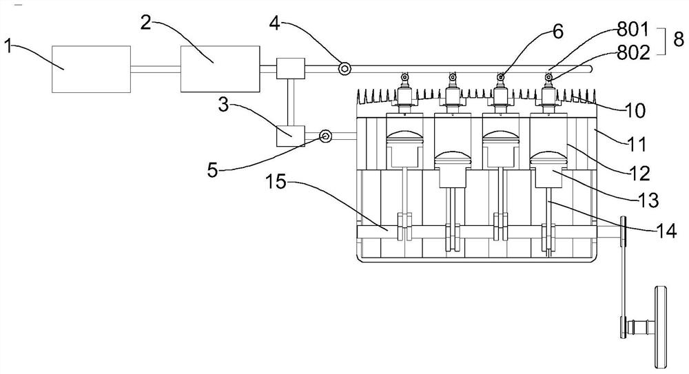
[0045] Please refer to figure 1 , figure 2 , this embodiment provides an embodiment of this application to provide a pneumatic engine, including:

[0046] engine casing 11;

[0047] Cylinder, the above-mentioned cylinder is horizontally arranged in the above-mentioned engine casing 11, and the above-mentioned cylinder forms a horizontal driving system, and the above-mentioned cylinder includes a cylinder block 12, and a piston 13 that is slidably arranged in the above-mentioned cylinder block 12, and the above-mentioned piston 13 is connected with a drive connection Rod 14, the free end of the above-mentioned driving connecting rod 14 is connected with a power output shaft 15, and the above-mentioned cylinder body 12 is also provided with an air inlet and an exhaust port;

[0048] Air intake assembly, the air intake assembly includes an electric air pump 1, the electric air pump 1 is connected with an air intake pipe 8, the free end of the air intake pipe 8 is connected wit...

Embodiment 2

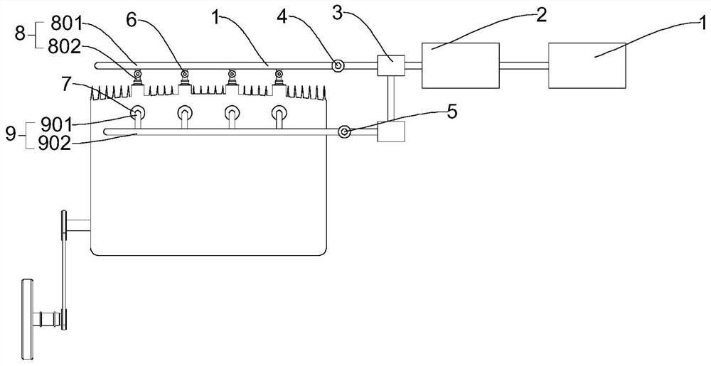
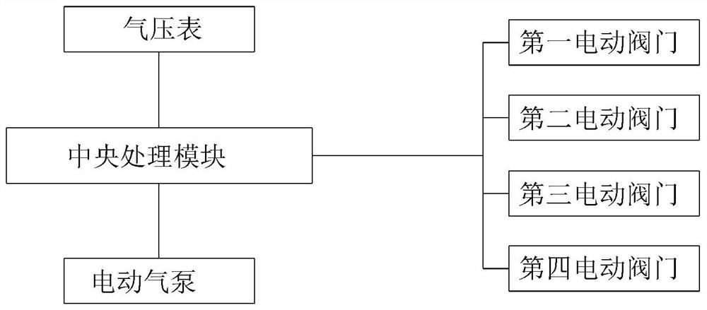
[0068] Please refer to Figure 1-Figure 3 , the present embodiment provides a control system of a pneumatic engine, including the above-mentioned pneumatic engine, and also includes a central processing module, and the central processing module is simultaneously connected with the first electric valve 4, the second electric valve 5, the third electric valve 6, The fourth electric valve 7 is connected with the above-mentioned electric air pump 1 .

[0069] The central processing unit (CPU, English: Central Processing Unit / Processor) is one of the main equipment of the electronic computer and the core accessory in the computer. Its function is mainly to interpret computer instructions and process data in computer software. All operations in the computer are the core components that the CPU is responsible for reading instructions, decoding instructions, and executing instructions. It can control the opening or closing of the first electric valve 4, the second electric valve 5, ...


PUM


Abstract

The invention provides a pneumatic engine and a control system, and relates to the field of automobile engines. The engine comprises an engine housing, a horizontal air cylinder, an air inlet assembly and an exhaust assembly; the horizontal air cylinder comprises a cylinder body and a piston, the piston is connected with a driving connecting rod, the driving connecting rod is connected with a power output shaft, and the cylinder body is further provided with an air inlet and an air outlet; the air inlet assembly comprises an electric air pump, the electric air pump is connected with an air inlet pipe, the air inlet pipe is connected with a first electric valve, and the first electric valve communicates with the air inlet; and the exhaust assembly comprises an exhaust pipe, the exhaust pipe communicates with the air outlet, and the exhaust pipe is provided with a second electric valve. The purpose of power output is achieved by pushing the piston to move through gas. The control system of the pneumatic engine comprises the pneumatic engine and further comprises a central processing module, the central processing module is connected with the first electric valve, the second electric valve, a third electric valve, a fourth electric valve and the electric air pump at the same time, and automatic inflation and exhaust of the air cylinder can be achieved.

Description

technical field [0001] The invention relates to the technical field of automobile engines, in particular to a pneumatic engine and a control system. Background technique [0002] The engine is the core part of the engine, so the engine is also commonly used to refer to the engine. The main part of the engine is the cylinder, which is also the source of power for the entire car. [0003] The main component of a traditional engine is the cylinder, which is the source of power for the entire car. Taking a diesel engine as an example, a diesel engine is an engine that burns diesel to obtain energy release. The cylinder of a diesel engine includes a cylinder block, an air intake hole, an oil delivery hole, Air outlet, piston. The working process of a diesel engine goes through four strokes: intake, compression, power, and exhaust. The fuel used in diesel engines is diesel oil, which has a higher viscosity than gasoline and is not easy to evaporate, but its auto-ignition temper...

Claims


Application Information

Patent Timeline
Patent Type & Authority Applications(China)
IPC IPC(8): F01B1/02F01B25/08F01B31/08
CPCF01B1/02F01B25/08F01B31/08
Inventor 陈丁
Owner 陈丁
Why Eureka
Try Eureka