
Internet-based shared power bank

A power bank and Internet technology, which is applied in the directions of location-based services, data exchange chargers, current collectors, etc. It can solve the problems of inability to accurately find the location of the transceiver cabinet, redundant billing, and limited number of charging slots in the transceiver cabinet.

Inactive Publication Date: 2021-11-30
深圳市微特芯科技有限公司
View PDF0 Cites 0 Cited by
  • Summary
  • Abstract
  • Description
  • Claims
  • Application Information

AI Technical Summary

Problems solved by technology

The current shared power bank is used in conjunction with the transceiver cabinet. Since the shared power bank has a certain degree of mobility, and the number of charging slots in the transceiver cabinet is limited, when the user borrows the shared power bank and returns the shared power bank after charging, Often encounter problems such as being unable to accurately find the location of the receiving and receiving cabinet, finding that the charging slot of the receiving and dispatching cabinet is full after finding the receiving and receiving cabinet, and excessive billing due to failure to return it in time
[0003] Therefore, it is necessary to design a shared power bank, which can enable users to quickly find the receiving and receiving cabinet, and when the user cannot find the available receiving and receiving cabinet in time, the billing can be suspended to avoid unnecessary charging.

Method used


Image

  • Internet-based shared power bank
  • Internet-based shared power bank
  • Internet-based shared power bank

Examples


Embodiment Construction

[0027] The following will clearly and completely describe the technical solutions in the embodiments of the present invention with reference to the accompanying drawings in the embodiments of the present invention. Obviously, the described embodiments are only some, not all, embodiments of the present invention. Based on the embodiments of the present invention, all other embodiments obtained by persons of ordinary skill in the art without making creative efforts belong to the protection scope of the present invention.

[0028] As introduced in the background technology, there are deficiencies in the prior art. In order to solve the above technical problems, this application proposes an Internet-based shared power bank.

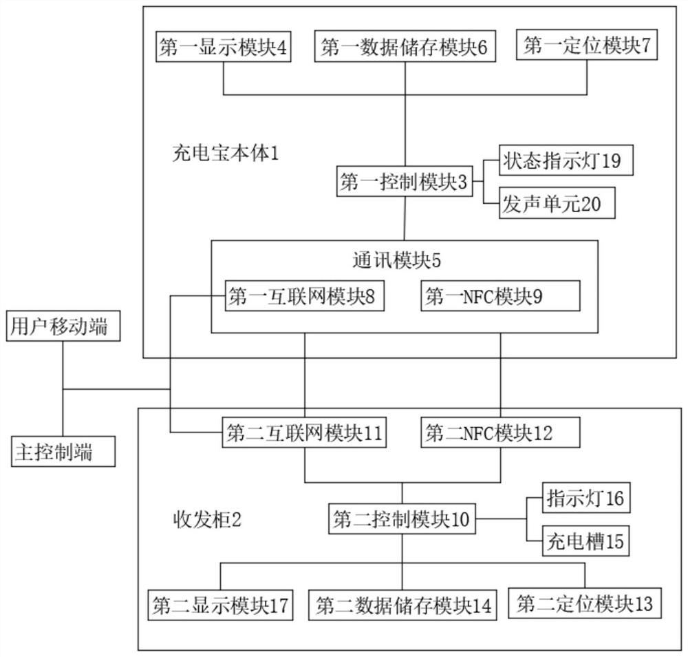
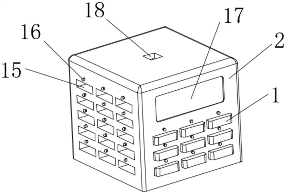
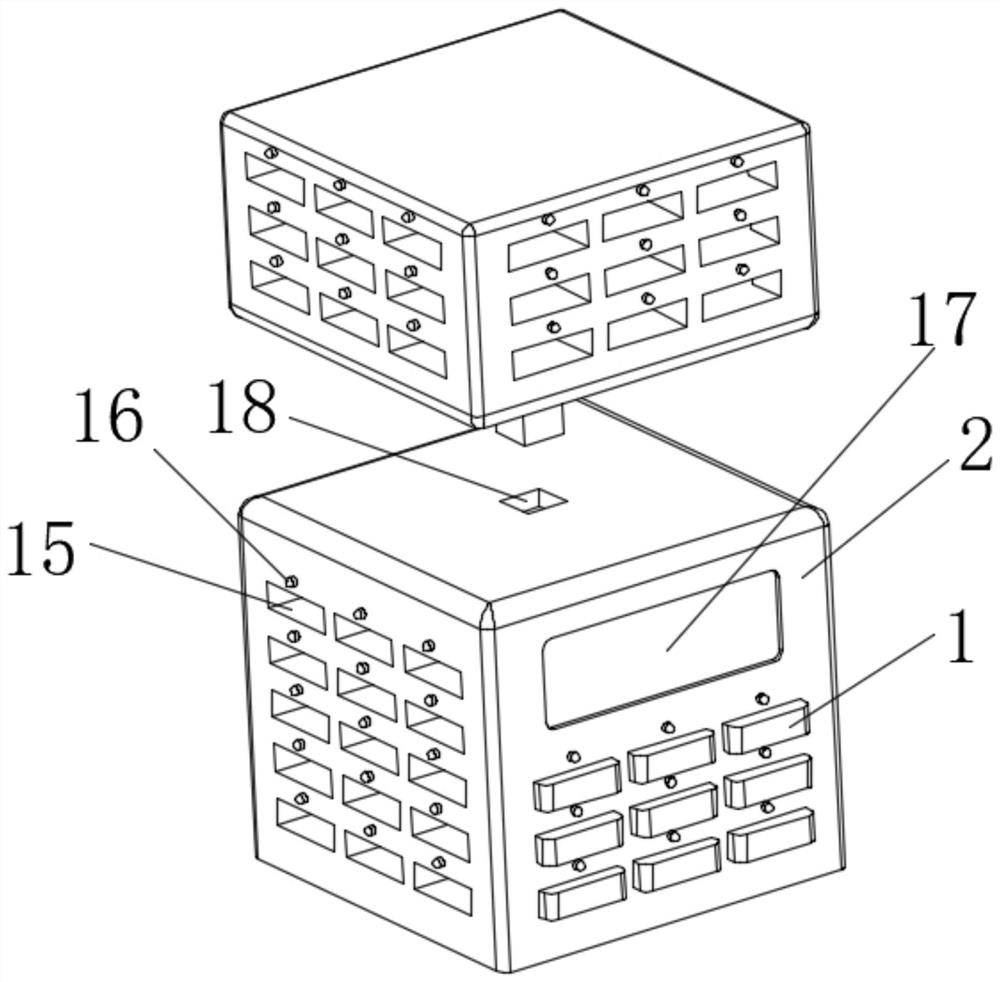
[0029] In a typical implementation of the present application, such as Figure 1-2 As shown, a shared power bank based on the Internet includes a power bank body 1 and a transceiver cabinet 2, and the power bank body 1 is provided with a first control module ...


PUM


Abstract

The invention belongs to the technical field of power banks and relates to an Internet-based shared power bank. The Internet-based shared power bankis provided with an Internet module, an NFC module and a positioning module. Through the positioning module, a user can quickly find a nearby shared power bank receiving and transmitting cabinet. The shared power bank communicates with the receiving and transmitting cabinet through the NFC module, when the receiving and transmitting cabinet is full, charging of the shared power bank is paused, and the nearest receiving and transmitting cabinet with vacancies is recommended to the user through the positioning module, so that the user can quickly find the receiving and transmitting cabinet with vacancies. Charging slots of the receiving and transmitting cabinets are numbered, so that the user can lock the empty charging slots of the nearest receiving and transmitting cabinet with vacancies through the Internet module, and the user can be ensured to smoothly return the shared power bank for the second time. The receiving and transmitting cabinet calculates the number of to-be-increased charging slots of the receiving and transmitting cabinet according to the information of the shared power bank recorded within a certain time, the charging slots of the receiving and transmitting cabinet can be expanded, the number of the charging slots of the receiving and transmitting cabinet is optimized, and the frequency that the user cannot return the shared power bank is reduced.

Description

technical field [0001] The invention relates to the technical field of shared power banks, in particular to an Internet-based shared power bank. Background technique [0002] Nowadays, electronic products are changing with each passing day, ranging from mobile phones to various wearable devices. When people travel, the battery life of electronic products is a problem that people pay special attention to. Every electronic product needs to be equipped with a charging device, which brings people travel. It is very inconvenient, so when people travel, they usually prepare charging treasures for the battery life of electronic products. In the general environment of the sharing economy, shared charging treasures can effectively solve the problem of battery life of people's travel electronic products, and can effectively improve the utilization rate of charging treasures. The current shared power bank is used in conjunction with the transceiver cabinet. Since the shared power bank...

Claims


Application Information

Patent Timeline
Patent Type & Authority Applications(China)
IPC IPC(8): G07F17/00H02J7/00H04W4/02H04W4/024H04W4/80
CPCG07F17/0042H02J7/00036H02J7/0013H02J7/0048H04W4/025H04W4/80H04W4/024Y02D30/70
Inventor 李海洋万里刘文标刘荣荣张文秀何皓弘彭土立
Owner 深圳市微特芯科技有限公司
Learn More