Display panel

A technology for display panels and sub-pixels, applied in static indicators, identification devices, instruments, etc., can solve the problems of high cost, low production efficiency, shortened service life, etc., to save production costs, improve production efficiency, and prolong service life. Effect

Active Publication Date: 2021-11-30
WUHAN CHINA STAR OPTOELECTRONICS SEMICON DISPLAY TECH CO LTD
View PDF6 Cites 0 Cited by
  • Summary
  • Abstract
  • Description
  • Claims
  • Application Information

AI Technical Summary

Problems solved by technology

[0005] The purpose of the present invention is to provide a display panel to solve the problem that each pixel unit in the existing organic light-emitting pixel structure only contains one blue sub-pixel, which causes the brightness of the blue sub-pixel to decay to the original brightness after long-term use. 70%-80%, at this time, the display effect is poor, which affects the technical problem of shortening the service life, and solves the technical problems of high cost and low production efficiency when each sub-pixel is separately produced in the organic light-emitting pixel structure of the existing display panel

Method used


Image

  • Display panel
  • Display panel
  • Display panel

Examples


Embodiment 1

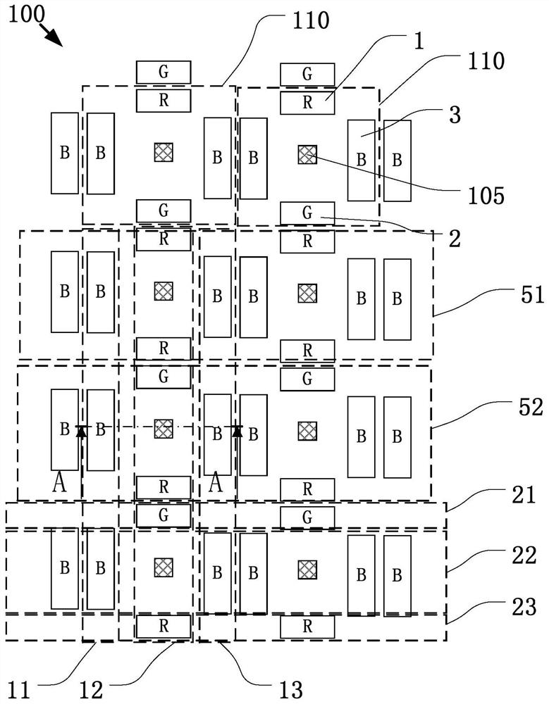
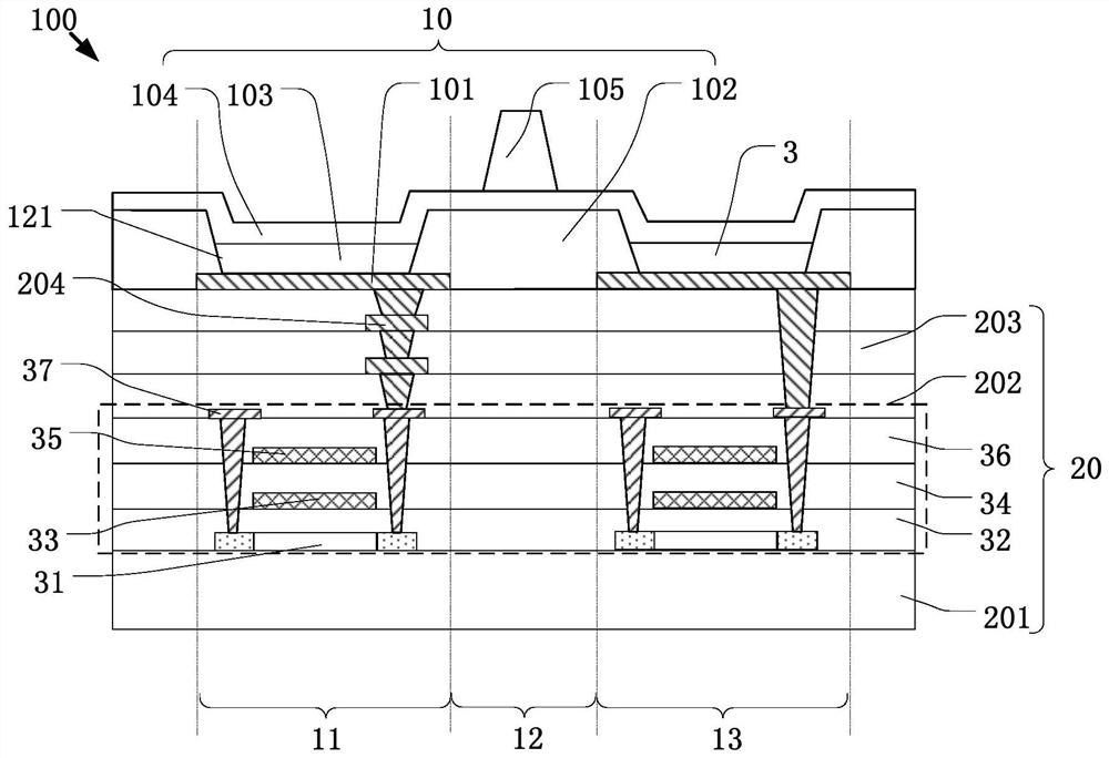
[0043] see Figure 1-Figure 3 As shown, the embodiment of the present invention provides a display panel 100 , including: an array substrate 20 ; a plurality of pixel units 110 disposed on the array substrate 20 ; and a data driving unit 40 . The data driving unit 40 is disposed on the array substrate 20 for providing a plurality of data signals to the plurality of pixel units 110 . Wherein, each pixel unit 110 includes one red sub-pixel 1 , one green sub-pixel 2 and two blue sub-pixels 3 . For the sake of brevity, R, G, and B are used in the drawings of this application to represent the red sub-pixel 1, the green sub-pixel 2, and the blue sub-pixel 3, respectively. The data driving unit 40 is used to drive the red sub-pixel 1, the green sub-pixel 2 and one of the blue sub-pixels 3 for image display, and drive the red sub-pixel after a default number of image frames 1. The green sub-pixel 2 and the other blue sub-pixel 3 perform image display. In this way, one of the blue s...

Embodiment 2

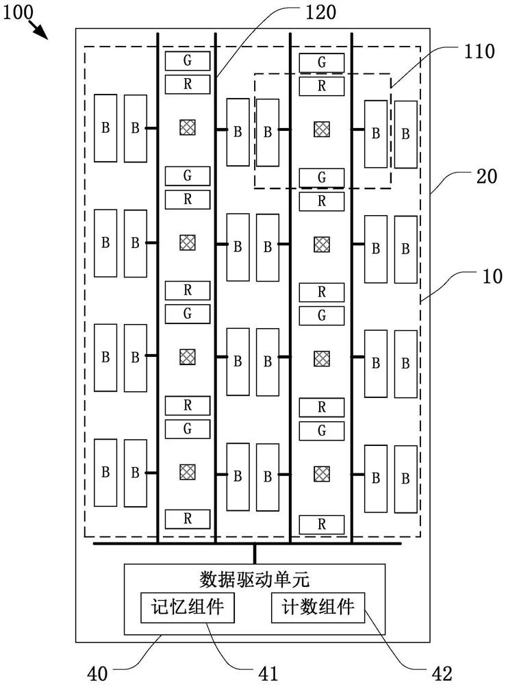
[0072] see Figure 4 As shown, Embodiment 2 includes most of the technical features of Embodiment 1. The difference is that in the pixel structure in Embodiment 2, a plurality of pixel units 110' are arranged to form odd rows 51, and a plurality of the The pixel units 110 are arranged to form even rows 52 , and the pixel units 110 ′ located in the odd rows 51 are arranged symmetrically with the pixel units 110 located in the even rows 52 .

[0073] Wherein in the second row, the second sub-pixel (G), the second sub-pixel, the third sub-pixel (R), the third sub-pixel, the second sub-pixel, the The second sub-pixels, the third sub-pixels, and the third sub-pixels are arranged alternately at intervals. Preferably, the light-emitting layers of two adjacent second sub-pixels are connected; the light-emitting layers of two adjacent third sub-pixels are connected. In this way, adjacent sub-pixels of the same color are prepared using the same mask opening. Structurally speaking, the...

Embodiment 3

[0076] see Figure 5 As shown, Embodiment 3 includes most of the technical features of Embodiment 1. The difference is that, in the pixel structure in Embodiment 3, each of the pixel units 110 defines sequentially arranged first sub-pixels The row 21 and the second sub-pixel row 22 do not include the third sub-pixel row 23 in the first embodiment.

[0077] see Figure 5 As shown, in Embodiment 3, the first sub-pixel row 21 includes one red sub-pixel 1, and the second sub-pixel row 22 includes one green sub-pixel 2; the blue sub-pixel 3 along Longitudinal across the first sub-pixel row 21 and the second sub-pixel row 22 .

[0078] see Figure 5 As shown, in Embodiment 3, both the second sub-pixel and the third sub-pixel are located between the first sub-pixel and the spare first sub-pixel.


PUM


Abstract

The invention provides a display panel. The display panel comprises: a plurality of first sub-pixels, which display a first color and are arranged in a first row along a first direction; a plurality of second sub-pixels, which display a second color and are arranged in a second row along the first direction; a plurality of third sub-pixels, which display a third color and are arranged in the second row along the first direction; and a plurality of standby first sub-pixels, which display the first color and arranged in a third row along the first direction, wherein the standby first sub-pixels and the adjacent first sub-pixels are driven in a time-sharing manner. The service life of the display panel is prolonged, and the problem that the service life is shortened due to the fact that the display effect is poor when only one blue sub-pixel is contained in each repeated pixel unit is solved. The adjacent light-emitting layers displaying the same color of sub-pixels are connected and prepared on an anode layer at the same time, so MASK opening difficulty can be reduced, process difficulty can be reduced, preparation steps are simplified, preparation cost is saved, and preparation efficiency is improved.

Description

technical field [0001] The present invention relates to the display field, in particular to a display panel. Background technique [0002] The 21st century is called a new "electronic information age". The development of the network has increased people's demand for information. Smart phones, watches, and tablet computers have become an indispensable part of people's lives. The advent of the information age has greatly promoted the development of display technology. People's pursuit of thinner and more energy-saving large-size, flexible displays has made organic electroluminescence become the mainstream of the market. [0003] For medium and large-sized products such as notebook computers, tablet computers, vehicle-mounted products, and TVs, the requirements for service life are relatively high, which poses a greater challenge to OLED panels, especially blue light devices with a short lifespan. [0004] At present, in the existing organic light-emitting pixel structure, eac...

Claims


Application Information

Patent Timeline
IPC IPC(8): G09F9/33G09G3/3208
CPCG09F9/33G09G3/3208
Inventor 王芳
Owner WUHAN CHINA STAR OPTOELECTRONICS SEMICON DISPLAY TECH CO LTD
Why Eureka
Try Eureka