Motor rotor winding equipment

A technology of motor rotor and equipment, applied in the field of motor rotor winding equipment, can solve the problems of impact damage, small contact friction area between the wheel and the ground, inconvenient adjustment of the height of the workbench, etc., and achieve the effect of reducing the impact force of vibration

Active Publication Date: 2021-11-30
常州市元瑞电机科技有限公司
View PDF8 Cites 0 Cited by
  • Summary
  • Abstract
  • Description
  • Claims
  • Application Information

AI Technical Summary

Problems solved by technology

[0004]1. It has the disadvantage of being inconvenient to move. It needs to manually lift the whole device when moving, which is time-consuming and laborious. However, due to the small contact friction area between the wheels and the ground, the parking is unstable; the simple installation of universal wheels with locks also lacks the buffering function when moving, and the vibration of the winding equipment when moving on uneven roads The impact force is relatively large, and it is easy to cause impact damage);
[0005]2. It has the disadvantage that it is not convenient to adjust the height of the workbench according to actual needs (it cannot be used comfortably by people of different heights), and cannot meet the needs of use. Therefore, we A kind of winding equipment for motor rotor is proposed to solve the above problems

Method used


Image

  • Motor rotor winding equipment
  • Motor rotor winding equipment
  • Motor rotor winding equipment

Examples


Embodiment

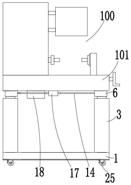
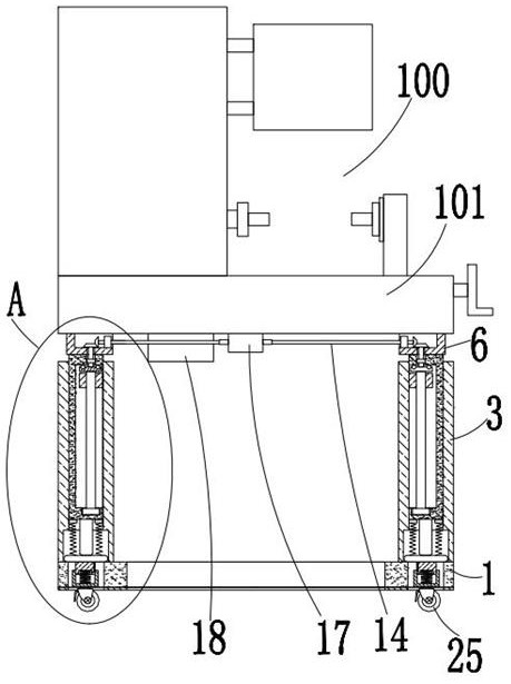
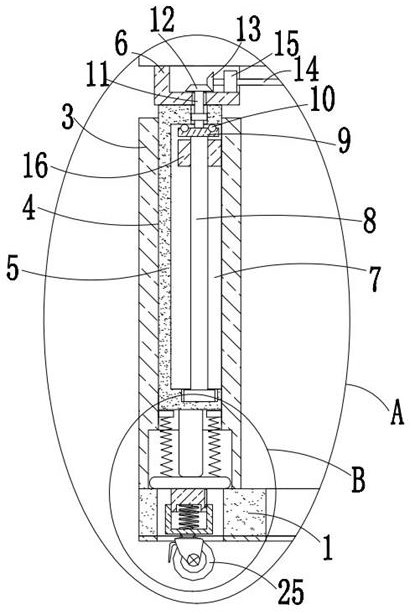
[0030] refer to Figure 1-5, this embodiment proposes a motor rotor winding device, including a motor rotor winding device body 100, the bottom of the motor rotor winding device body 100 is fixedly connected with a workbench 101, and the bottom of the workbench 101 is provided with a circular shape The base 1 and both sides of the top of the back-shaped base 1 are fixedly connected with support plates 3, the top of the support plate 3 is provided with a rectangular groove 4, and the sliding sleeve in the rectangular groove 4 is provided with a rectangular plate 5, and the top of the rectangular plate 5 extends to the corresponding The top of the support plate 3 is fixedly connected with a rectangular box 6 with an opening at the top, and the sides of the two rectangular boxes 6 close to each other are all set as openings, and the top of the rectangular box 6 is fixedly connected with the bottom of the workbench 101. The sides of the rectangular plates 5 that are close to each ...


PUM


Abstract

The invention discloses motor rotor winding equipment, which comprises a motor rotor winding equipment body. A workbench is fixedly connected to the bottom of the motor rotor winding equipment body, a concentric-square-shaped base is arranged below the workbench, supporting plates are fixedly connected to the two sides of the top of the concentric-square-shaped base, and rectangular grooves are formed in the tops of the supporting plates; a rectangular plate is slidably arranged in the rectangular groove in a sleeved mode, and the top of the rectangular plate extends to the position above the corresponding supporting plate and is fixedly connected with a rectangular box with an opening in the top. According to the motor rotor winding equipment, the motor rotor winding equipment body can be conveniently moved, buffering is conveniently conducted during moving, the hard shock impact damage risk caused to the motor rotor winding equipment body when the motor rotor winding equipment body moves on an uneven road surface is reduced, and storage of the walking wheels and height adjustment of the workbench are conveniently achieved through single drive; the supporting friction area between the bottom and the ground during parking is increased, parking stability is improved, use requirements are met, and use is facilitated.

Description

technical field [0001] The invention relates to the technical field of motor rotor winding equipment, in particular to a motor rotor winding equipment. Background technique [0002] Motor rotor: It is also a rotating part in the motor. The motor is composed of two parts: the rotor and the stator. It is a conversion device used to realize electrical energy and mechanical energy and mechanical energy and electrical energy. The motor rotor is divided into a motor rotor and a generator rotor. The motor rotor is wound During processing, a rotor winding device is required for winding; after searching, the authorized announcement number CN211744296U discloses an automatic winding equipment for a motor rotor, including a workbench, and a rotating assembly is arranged inside the workbench, and the workbench A box is fixedly installed on the top of the top and away from the rotating assembly, and a motor is fixedly installed inside the box, and a short rod is fixedly installed on the ...

Claims


Application Information

Patent Timeline
IPC IPC(8): H02K15/04H02K15/08
CPCH02K15/0435H02K15/08
Inventor 丁晓军
Owner 常州市元瑞电机科技有限公司
Why Eureka
Try Eureka