Circulating sewage treatment device capable of avoiding blockage
A sewage treatment device, technology for avoiding clogging, applied in the direction of fixed filter element filter, filtration separation, dissolution, etc., can solve the problems of reducing sewage treatment efficiency, affecting the normal use of equipment, clogging filter nets, etc., to improve sewage treatment effect, Improve the efficiency of sewage treatment and avoid clogging
- Summary
- Abstract
- Description
- Claims
- Application Information
AI Technical Summary
Problems solved by technology
Method used
Image

Examples
Embodiment 1
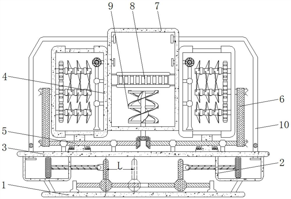
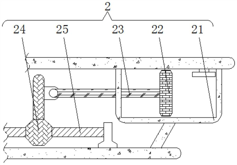
[0018] see figure 1 , figure 2 , a pneumatic mechanism 2 is arranged above the bottom plate 1, and the pneumatic mechanism 2 includes a sealed cabin 21. The inside of the sealed cabin 21 is slidably connected with a pressure plate 22, the side of the pressure plate 22 is hinged with a push rod 23, and the end of the push rod 23 away from the pressure plate 22 is hinged with a The sliding sleeve 24, the inner part of the sliding sleeve 24 is rotatably connected with a screw rod 25; the pneumatic mechanism 2 is provided with two groups with the same internal structure and specifications, and the two groups of pneumatic mechanisms 2 are symmetrically distributed with the midpoint of the base plate 1 as the center, and the pressure plate 22 The size of the seal is adapted to the size of the interior of the sealed compartment 21;
[0019] The sliding sleeve 24 and the pressing plate 22 are welded by the ejector rod 23, and the screw rod 25 is connected to the top of the bottom pl...
Embodiment 2
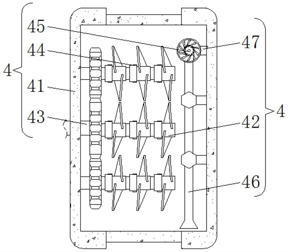
[0022] see figure 1 , image 3 , a pneumatic mechanism 2 is arranged above the bottom plate 1, a mounting plate 3 is welded on the top of the pneumatic mechanism 2, and a circulation mechanism 4 is welded on the top of the mounting plate 3. The circulation mechanism 4 includes a stirring bin 41, and the interior of the stirring bin 41 is rotatably connected with a stirring Rod one 42, the side of stirring rod one 42 is welded with stirring shaft 43, the side of stirring rod one 42 is engaged with stirring rod two 44, the side of stirring bin 41 is provided with water pump 45, and the bottom of water pump 45 is welded with suction pipe 46, A drain pipe 47 is welded on the side of the water pump 45;
[0023] The circulation mechanism 4 is provided with two groups and has the same internal structure and specifications. The two groups of circulation mechanisms 4 are distributed in symmetrical positions with the filter bin 7 as the center. They are meshed on the upper and lower s...
Embodiment 3
[0026] see Figure 1-3 , a pneumatic mechanism 2 is arranged above the bottom plate 1, and the pneumatic mechanism 2 includes a sealed cabin 21. The inside of the sealed cabin 21 is slidably connected with a pressure plate 22, the side of the pressure plate 22 is hinged with a push rod 23, and the end of the push rod 23 away from the pressure plate 22 is hinged with a The sliding sleeve 24, the inner part of the sliding sleeve 24 is rotatably connected with a screw rod 25; the pneumatic mechanism 2 is provided with two groups with the same internal structure and specifications, and the two groups of pneumatic mechanisms 2 are symmetrically distributed with the midpoint of the base plate 1 as the center, and the pressure plate 22 The size of the airtight chamber 21 is adapted to the internal size of the sealing chamber 21, the sliding sleeve 24 and the pressure plate 22 are welded by the ejector rod 23, the screw rod 25 is horizontally connected to the top of the bottom plate 1,...
PUM
 Abstract
Description
Claims
Application Information
 - R&D
- Intellectual Property
- Life Sciences
- Materials
- Tech Scout
- Unparalleled Data Quality
- Higher Quality Content
- 60% Fewer Hallucinations
Browse by: Latest US Patents, China's latest patents, Technical Efficacy Thesaurus, Application Domain, Technology Topic, Popular Technical Reports.
© 2025 PatSnap. All rights reserved.Legal|Privacy policy|Modern Slavery Act Transparency Statement|Sitemap|About US| Contact US: help@patsnap.com