a fluid storage tank
A storage tank and fluid technology, applied in the field of paints and coatings, can solve the problems of not being used as a daily paint storage device, affecting the function of storing paint, waste, etc., so as to avoid the loss of pistons, improve work efficiency, and facilitate use.
- Summary
- Abstract
- Description
- Claims
- Application Information
AI Technical Summary
Problems solved by technology
Method used
Image
Examples
Embodiment 1
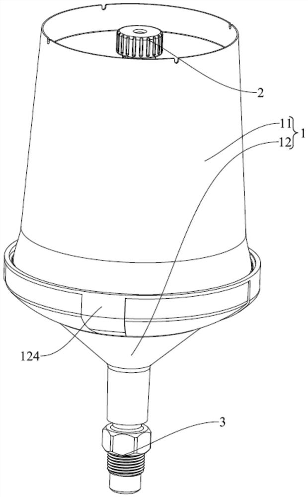
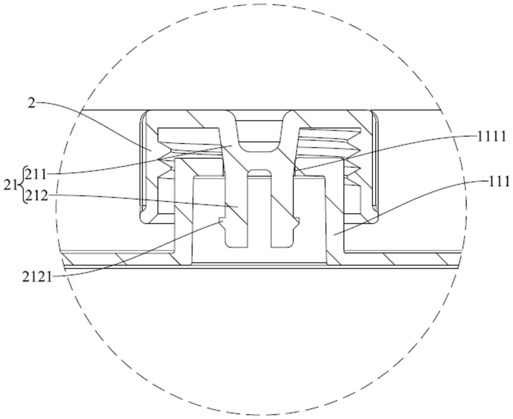
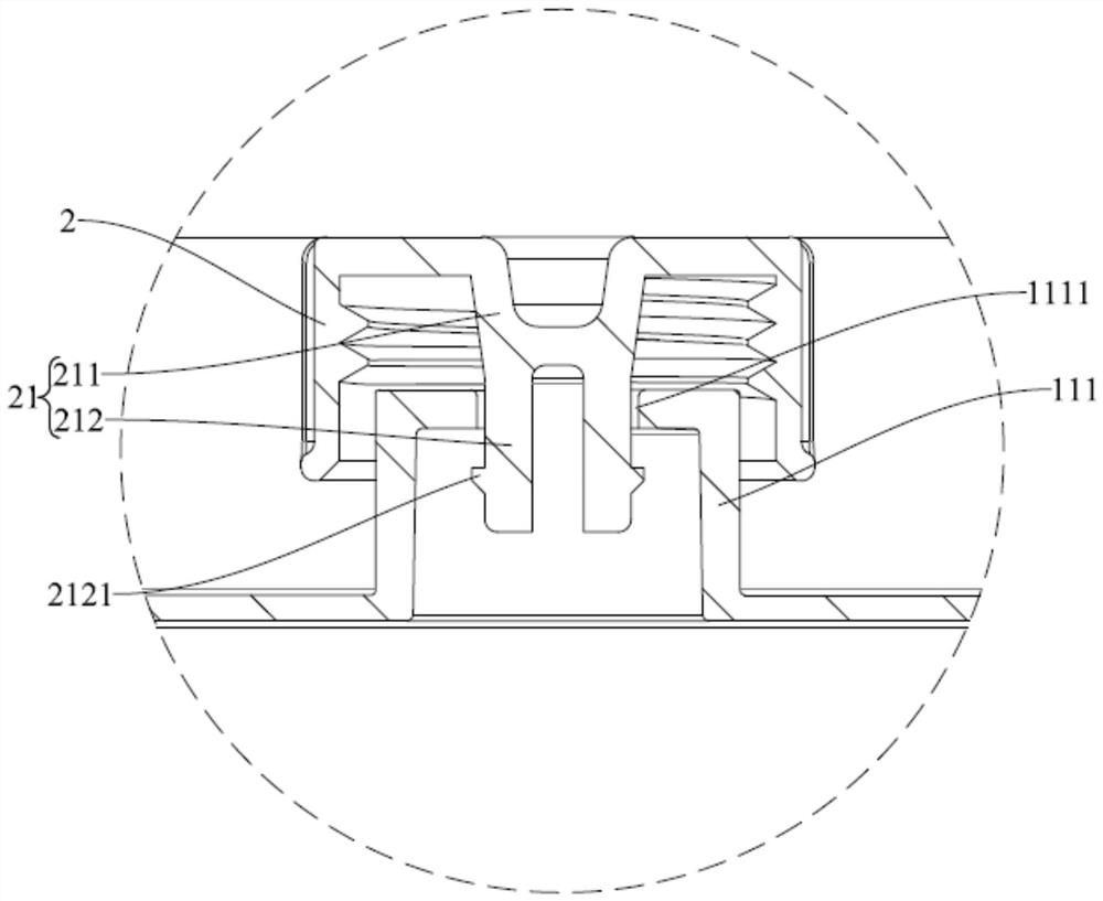
[0067] Reference below Figure 1-Figure 5 The fluid storage tank provided by the first embodiment of the present invention is described.
[0068] The fluid storage tank provided in this embodiment includes a tank body 1 , a venting piston 2 and an adapter 3 , and the tank body 1 includes a kettle body 11 and a kettle lid 12 . One end of the kettle body 11 is open and the other end is closed. The closed end of the kettle body 11 is provided with a protruding part 111 and an elastic arm 112. An air inlet 1111 is formed on the bottom wall of the protruding part 111. The peripheral wall is provided with matching threads, and the pot cover 12 is fastened on the pot body 11 and is threadedly connected with the pot cover 12 . An output pipe 121 is provided at one end of the pot lid 12 away from the pot body 11 , the inlet end of the output pipe 121 has an annular protrusion 123 , and the outlet end has a locking thread 122 . The elastic arm 112 is provided with an anti-rotation pro...
Embodiment 2
[0071] Reference below Figure 6-Figure 7 The fluid storage tank provided by the second embodiment of the present invention is described.
[0072] The fluid storage tank provided in this embodiment includes a tank body 1 , a venting piston 2 and an adapter 3 , and the tank body 1 includes a kettle body 11 and a kettle lid 12 . One end of the pot body 11 is open and the other end is closed. The pot lid 12 is fastened on the pot body 11 and is threadedly connected with the pot lid 12. An output pipe 121 is provided at the end of the pot lid 12 away from the pot body 11. The inlet end of the output pipe 121 has an annular protrusion 123, and the outlet end has a lock Tighten thread 122. The adapter 3 includes a ball head section 33, a base section 34 and a locking section 35. The ball head section 33 is at one end away from the ball head, inserted into the output tube 121 and sleeved on the annular protrusion 123, and the ball head section 33 is provided with There is a third ...
Embodiment 3
[0074] Reference below Figure 8-Figure 9 The fluid storage tank provided by the third embodiment of the present invention is described.
[0075] The fluid storage tank provided in this embodiment includes a tank body 1, a venting piston 2 and an adapter 3. The tank body 1 includes a kettle body 11 and a lid 12. One end of the kettle body 11 is open and the other end is closed. The pot lid 12 is fastened on the pot body 11 and connected with the pot body 11 by threads. The end of the pot lid 12 away from the pot body 11 is provided with an output pipe 121 , and an annular groove 1211 is provided on the outer peripheral wall of the output pipe 121 . The adapter 3 includes a body 36 , a fixing ring 37 , an elastic member 38 , a locking ring 39 and an operating ring 310 . The main body 36 is sleeved on the output pipe 121 , the main body 36 is provided with positioning balls 320 distributed along its circumferential direction, the positioning balls 320 are fitted in the annular ...
PUM
 Abstract
Description
Claims
Application Information
 - R&D
- Intellectual Property
- Life Sciences
- Materials
- Tech Scout
- Unparalleled Data Quality
- Higher Quality Content
- 60% Fewer Hallucinations
Browse by: Latest US Patents, China's latest patents, Technical Efficacy Thesaurus, Application Domain, Technology Topic, Popular Technical Reports.
© 2025 PatSnap. All rights reserved.Legal|Privacy policy|Modern Slavery Act Transparency Statement|Sitemap|About US| Contact US: help@patsnap.com


