Hydraulic actuator for hydraulic foot type robot

A hydraulic actuation and robot technology, which is applied in the direction of motor vehicles, manipulators, manufacturing tools, etc., can solve the problems of uncontrollable variable stiffness, impact force buffering and low impact energy recovery and reuse ability, so as to increase adaptability and improve mechanism Life, impact reduction effect

Active Publication Date: 2021-12-03
HARBIN INST OF TECH
View PDF3 Cites 0 Cited by
  • Summary
  • Abstract
  • Description
  • Claims
  • Application Information

AI Technical Summary

Problems solved by technology

[0005] The present invention overcomes the uncontrollable variable stiffness, impact force buffering and recovery and reuse of impact energy in the hydraulic actuator in the hydraulic foot robot of the prior art The problem of low capacity, and then provide a hydraulic actuator for hydraulic foot robots

Method used


Image

  • Hydraulic actuator for hydraulic foot type robot
  • Hydraulic actuator for hydraulic foot type robot
  • Hydraulic actuator for hydraulic foot type robot

Examples


specific Embodiment approach 1

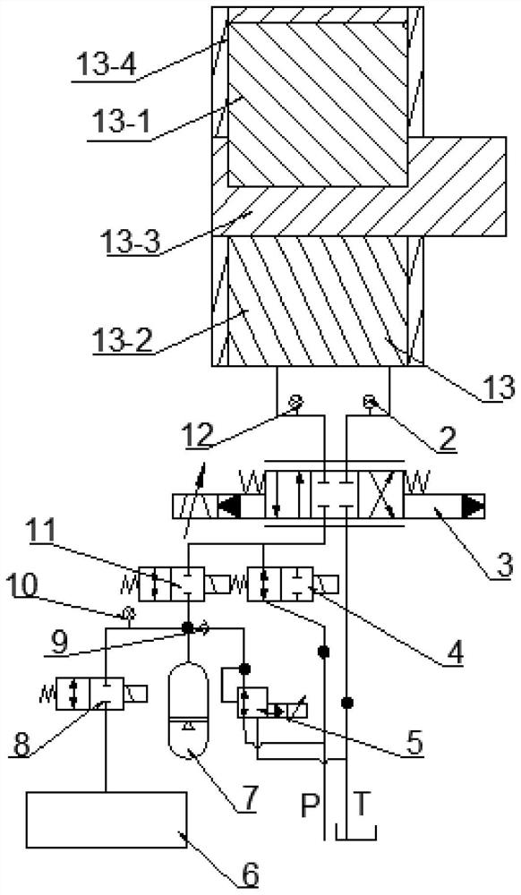
[0023] Specific implementation mode one: combine Figure 1 to Figure 5 Describe this embodiment, a hydraulic actuator for a hydraulic foot robot in this embodiment, which includes a hydraulic actuator and a hydraulic unit;

[0024] The hydraulic actuator is located above the hydraulic unit;

[0025] The hydraulic unit includes servo valve 3, No. 1 high-speed switching valve 4, electromagnetic pressure reducing valve 5, other hydraulic system components 6, accumulator 7, No. 3 high-speed switching valve 8, No. 2 high-speed switching valve 11 and high-pressure oil source P;

[0026] The nozzles of the two upper oil circuits of the servo valve 3 are respectively connected to the oil inlet and the oil outlet of the hydraulic actuator, and one lower oil circuit of the servo valve 3 is provided with a parallel connection with the upper oil circuit of No. 1 high-speed switching valve 4. The upper oil circuit of the No. 2 high-speed on-off valve 11, the lower oil circuit of the No. ...

specific Embodiment approach 2

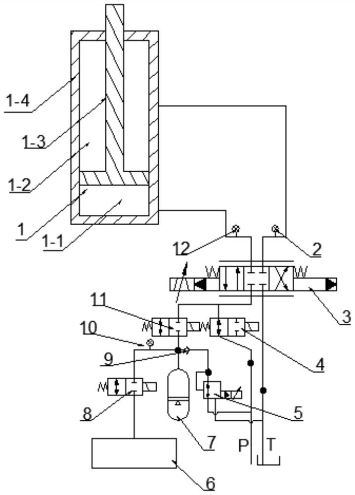
[0029] Specific implementation mode two: combination Figure 1 to Figure 5 Describe this embodiment, it also comprises low-pressure fuel tank T of this embodiment,

[0030] The other lower end oil circuit of the servo valve 3 is provided with a low pressure oil tank T connected in parallel with the upper end oil circuit of the high pressure oil source P.

[0031] Others are the same as the first embodiment.

specific Embodiment approach 3

[0032] Specific implementation mode three: combination Figure 1 to Figure 5 Describe this embodiment, it also comprises check valve 9 of this embodiment,

[0033] A check valve 9 is arranged on the connecting pipeline between the upper end oil circuit of the electromagnetic pressure reducing valve 5 and the oil circuit of the accumulator 7 .

[0034] Others are the same as those in Embodiment 1 or 2.


PUM


Abstract

The invention discloses a hydraulic actuator for a hydraulic foot type robot, in particular to a hydraulic actuator which aims at solving the problems that in the prior art, a hydraulic actuator in a hydraulic foot type robot is uncontrollable in variable rigidity and low in impact force buffering and impact energy recycling and reusing capacity. Pipe orifices of two upper-end oil ways of a servo valve are respectively connected with an oil inlet and an oil outlet of the hydraulic actuator; one lower-end oil path of the servo valve is provided with an upper-end oil way of a second high-speed switch valve connected with an upper-end oil way of a first high-speed switch valve in parallel; a lower-end oil way of the first high-speed switch valve is provided with an upper-end oil way of a high-pressure oil source connected with a lower-end oil way of an electromagnetic pressure reducing valve in parallel; the upper-end oil way of the electromagnetic pressure reducing valve is connected with an oil way of an energy accumulator; a lower-end oil way of the second high-speed switch valve is provided with an oil way of the energy accumulator connected with the upper-end oil way of the electromagnetic pressure reducing valve in parallel and an upper-end oil way of a third high-speed switch valve; and the hydraulic actuator can directly move or swing under the action of a hydraulic unit.

Description

technical field [0001] The invention relates to the technical field of industrial production, in particular to a hydraulic actuator for a hydraulic leg robot. Background technique [0002] Legged robots, such as single-legged robots, bipedal robots, quadrupedal robots, and more legged robots, touch the ground in the form of foot endpoints during running or jumping, and produce a huge point-surface gap from the flight phase to the landing. Collision impact, if the impact force is not effectively buffered, the leg-foot mechanism of the legged robot will be damaged quickly due to the impact and greatly affect the running stability of the legged robot. Therefore, elastic springs such as springs are usually installed on the legs of the legged robot elements to fully cushion the impact. From the perspective of bionics, the overall stiffness of the leg movement mechanism of legged animals is different at different jump heights and running speeds. For example, the tension of the th...

Claims


Application Information

Patent Timeline
Patent Type & Authority Applications(China)
IPC IPC(8): B25J19/00B62D57/032
CPCB25J19/0025B62D57/032
Inventor 丛大成李加启杨志东杨宇张燕燕江磊
Owner HARBIN INST OF TECH
Why Eureka
Try Eureka