
Manipulator camera setting structure

A camera and manipulator technology, applied in the field of robotics, can solve problems such as loose installation, affecting the shooting effect of the camera module, and looseness, and achieve the effects of improving locking strength and stability, improving shooting clarity, and preventing loosening

Inactive Publication Date: 2021-12-03
SHANGHAI GEZHI HIGH SCHOOL
View PDF0 Cites 1 Cited by
  • Summary
  • Abstract
  • Description
  • Claims
  • Application Information

AI Technical Summary

Problems solved by technology

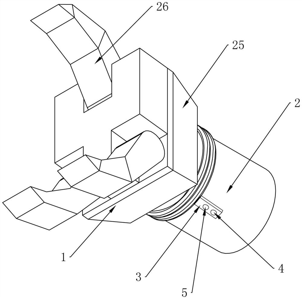
[0006] In view of the above-mentioned problem that the installation between the camera module on the existing manipulator and the manipulator is not firm or loose, thus affecting the shooting effect of the camera module, it is now intended to provide a camera setting structure for the manipulator, through the locking mechanism, from all directions Lock the active position of the camera base, so as to realize the stability of the camera and improve the shooting effect of the camera

Method used


Image

  • Manipulator camera setting structure
  • Manipulator camera setting structure
  • Manipulator camera setting structure

Examples


Embodiment approach

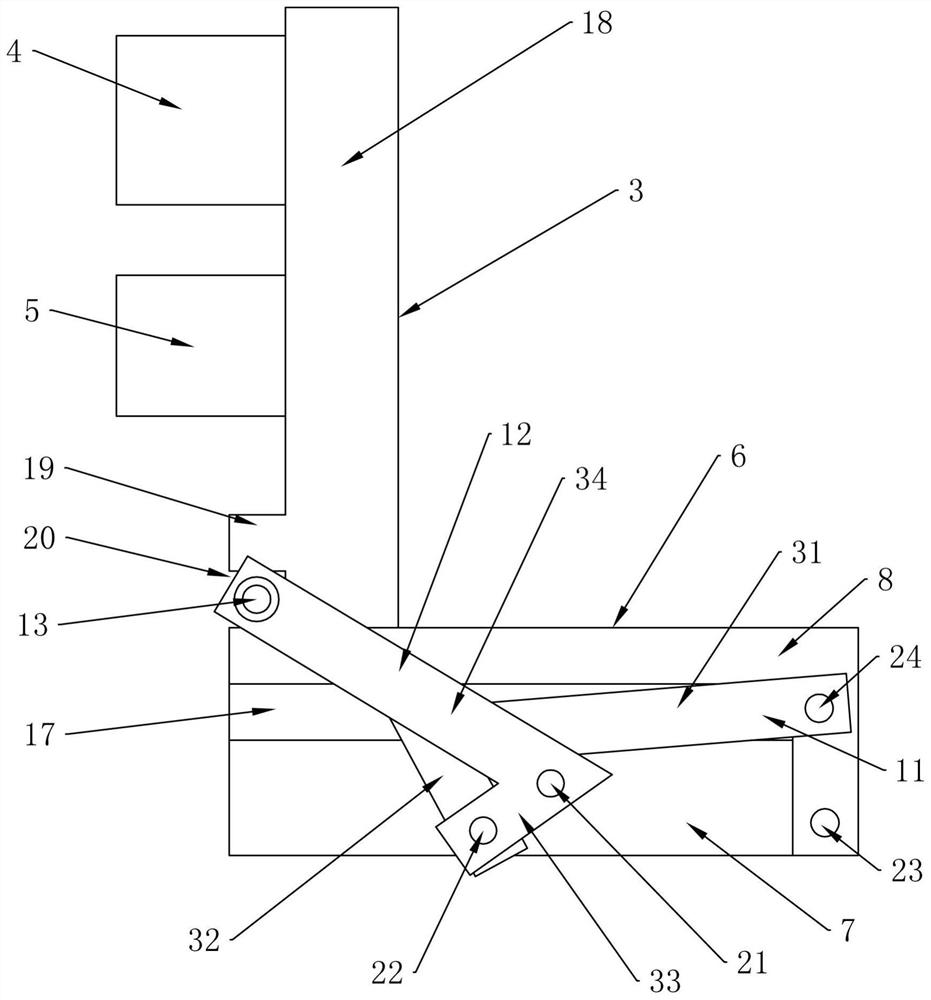
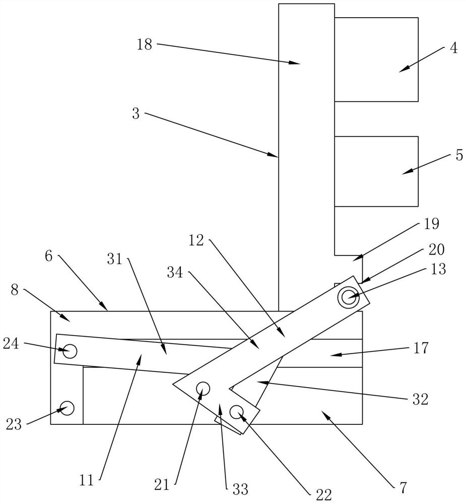
[0051] In further embodiments of the present invention, please continue to refer to Figure 1 to Figure 7 As shown, the first connecting rod 11 includes a first rotating rod part 31 and a second rotating rod part 32 connected in sequence, one end of the first rotating rod part 31 is rotationally connected with the end of one side of the second mounting plate 8, and the second The other end of a rotating rod part 31 is fixedly connected with one end of the second rotating rod part 32, a first included angle is formed between the first rotating rod part 31 and the second rotating rod part 32, and the first rotating rod part 31 and the second rotating rod part The connection of the two rotating rod parts 32 is limited fit with the first rotating shaft 21 .

[0052] In a further embodiment of the present invention, the second connecting rod 12 includes a third rotating rod part 33 and a fourth rotating rod part 34 connected in sequence, and one end of the third rotating rod part 3...


PUM


Abstract

The invention discloses a manipulator camera setting structure, and belongs to the technical field of robots. The manipulator camera setting structure comprises a manipulator and a mechanical arm transmission shaft, wherein the mechanical arm transmission shaft is in transmission connection with the manipulator; the manipulator camera setting structure further comprises a camera base, a first camera and a second camera, the camera base is fixedly connected with the mechanical arm transmission shaft through a locking mechanism, the first camera and the second camera are arranged on the camera base, and the first camera and the second camera face the manipulator; and the side wall of the mechanical arm transmission shaft is provided with a mounting space, and the locking mechanism is arranged in the mounting space. According to the manipulator camera setting structure, the moving position of the camera base is locked from all directions through the locking mechanism, so that the stability of the cameras is realized, and the shooting effect and definition of the cameras are improved.

Description

technical field [0001] The invention relates to the technical field of robots, in particular to a camera arrangement structure of a manipulator. Background technique [0002] A robot is a machine device that performs work automatically. It can accept human commands, run pre-programmed programs, and act according to principles and programs formulated with artificial intelligence technology. The task of robots is to assist or replace humans in work, such as manufacturing, construction, or dangerous work. [0003] Intelligent robots have various internal information sensors and external information sensors, such as vision, hearing, touch, and smell. In addition to having receptors, it also has effectors as a means of acting on its surroundings. These are the muscles, or self-synchronizing motors, which move the hands, feet, proboscis, antennae, and so on. It can also be seen from this that an intelligent robot must have at least three elements: sensory elements, reaction ele...

Claims


Application Information

Patent Timeline
Patent Type & Authority Applications(China)
IPC IPC(8): B25J19/02B25J19/00
CPCB25J19/023B25J19/00
Inventor 胡健顾亦雯
Owner SHANGHAI GEZHI HIGH SCHOOL
Learn More