Cantilever beam crane
A crane and cantilever beam technology, applied in the field of cantilever beam cranes, can solve problems such as troublesome injection of lubricating oil
- Summary
- Abstract
- Description
- Claims
- Application Information
AI Technical Summary
Problems solved by technology
Method used
Image
Examples
Embodiment 1
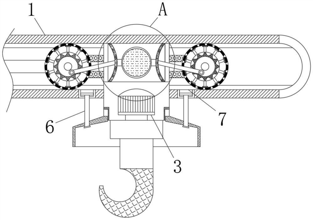
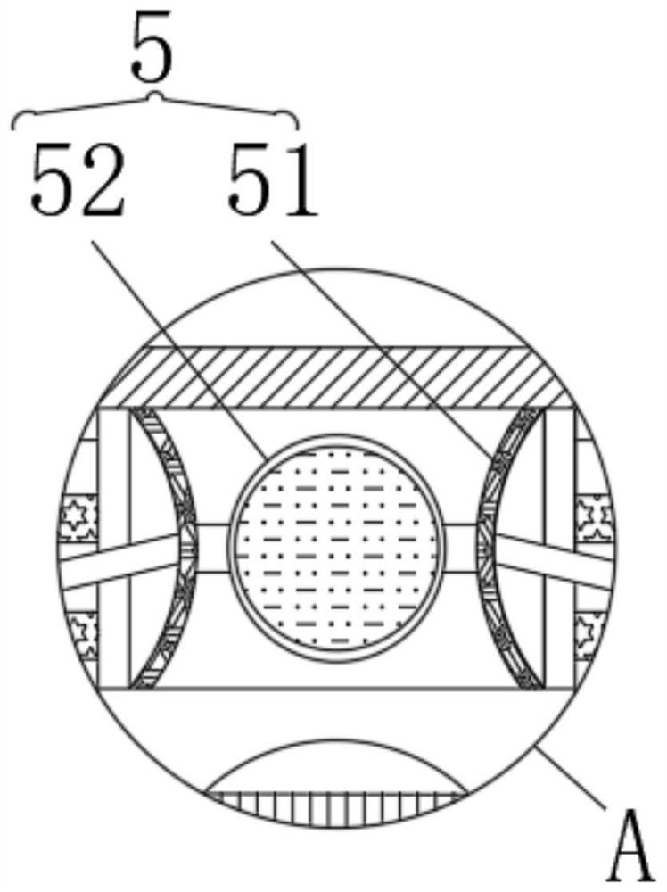
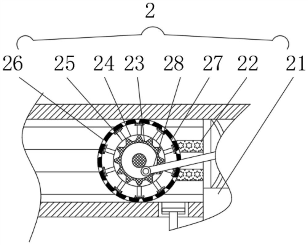
[0027] see Figure 1-3 , a cantilever beam crane, comprising a fixed plate 1, the inside of the fixed plate 1 and the inside of the connecting plate 21 are fixedly installed with a liquid storage mechanism 5, and the liquid storage mechanism 5 includes: an elastic plate 51, the elastic plate 51 A liquid storage bag 52 is fixedly installed on the opposite surface, and the connection relationship between the liquid storage bag 52 and the liquid storage ring 26 is designed to be connected. The inside of the fixed plate 1 is fixedly installed with a liquid injection mechanism 2, and the liquid injection mechanism 2 Including: connecting plate 21, the left and right ends of the connecting plate 21 are connected to the rotating wheel 23 through the support plate 22, the outer end of the rotating wheel 23 is fixedly installed with a fixed ring 24, the outer end of the fixed ring 24 Evenly distributed brush rods 25 are fixedly installed, and the outer end of the rotating wheel 23 and ...
Embodiment 2
[0029] see figure 1 , 2 , 4, a cantilever beam crane, comprising a fixed plate 1, the inside of the fixed plate 1 is fixedly installed with a liquid injection mechanism 2, the lower end of the fixed plate 1 is fixedly installed with a drive device 3, the lower end of the drive device 3 Rotation is connected with adjustment mechanism 4, and adjustment mechanism 4 comprises: rotation block 41, and the connection relation between rotation block 41 and connecting plate 21 is rotation connection, and the upper end of rotation block 41 and the bottom end of fixed plate 1 are slidingly connected with sliding. Rod 6, the end face of the fixed plate 1 in contact with the sliding rod 6 is provided with a limiting groove 7, the connection relationship between the limiting groove 7 and the sliding rod 6 is a sliding connection, and the lower end of the rotating block 41 is fixedly installed There is a suspension hook 42, and the left and right ends of the rotating block 41 are fixedly eq...
Embodiment 3
[0031] see Figure 1-4, a cantilever beam crane, comprising a fixed plate 1, the inside of the fixed plate 1 and the inside of the connecting plate 21 are fixedly installed with a liquid storage mechanism 5, and the liquid storage mechanism 5 includes: an elastic plate 51, the elastic plate 51 A liquid storage bag 52 is fixedly installed on the opposite surface, and the connection relationship between the liquid storage bag 52 and the liquid storage ring 26 is designed to be connected. The inside of the fixed plate 1 is fixedly installed with a liquid injection mechanism 2, and the liquid injection mechanism 2 Including: connecting plate 21, the left and right ends of the connecting plate 21 are connected to the rotating wheel 23 through the support plate 22, the outer end of the rotating wheel 23 is fixedly installed with a fixed ring 24, the outer end of the fixed ring 24 Evenly distributed brush rods 25 are fixedly installed, and the outer end of the rotating wheel 23 and t...
PUM
 Abstract
Description
Claims
Application Information
 - R&D
- Intellectual Property
- Life Sciences
- Materials
- Tech Scout
- Unparalleled Data Quality
- Higher Quality Content
- 60% Fewer Hallucinations
Browse by: Latest US Patents, China's latest patents, Technical Efficacy Thesaurus, Application Domain, Technology Topic, Popular Technical Reports.
© 2025 PatSnap. All rights reserved.Legal|Privacy policy|Modern Slavery Act Transparency Statement|Sitemap|About US| Contact US: help@patsnap.com


