Turning gear

A technology of turning gear and mounting holes, which is applied to engine components, machines/engines, mechanical equipment, etc., can solve the problem of low work efficiency, and achieve the effect of satisfying disassembly or maintenance and ensuring normal work.

Pending Publication Date: 2021-12-03
雨凡机械科技(上海)有限公司
View PDF0 Cites 0 Cited by
  • Summary
  • Abstract
  • Description
  • Claims
  • Application Information

AI Technical Summary

Problems solved by technology

[0003] The main purpose of the present invention is to provide a turning device, aiming at solving the technical problem of low working efficiency of the existing turning device

Method used


Image

  • Turning gear
  • Turning gear
  • Turning gear

Examples


Embodiment Construction

[0034] The technical solutions in the embodiments of the present invention will be clearly and completely described below with reference to the accompanying drawings in the embodiments of the present invention. Obviously, the described embodiments are only a part of the embodiments of the present invention, not all of the embodiments. Based on the embodiments of the present invention, all other embodiments obtained by those of ordinary skill in the art without creative work fall within the protection scope of the embodiments of the present invention.

[0035] It should be noted that all directional indications (such as up, down, left, right, front, back, etc.) in the embodiments of the present invention are only used to explain the relationship between various components under a certain posture (as shown in the accompanying drawings). The relative positional relationship, the movement situation, etc., if the specific posture changes, the directional indication also changes acco...


PUM


Abstract

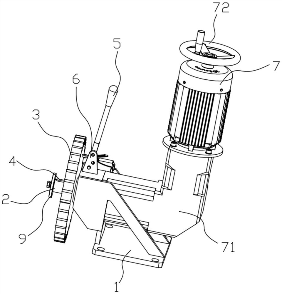
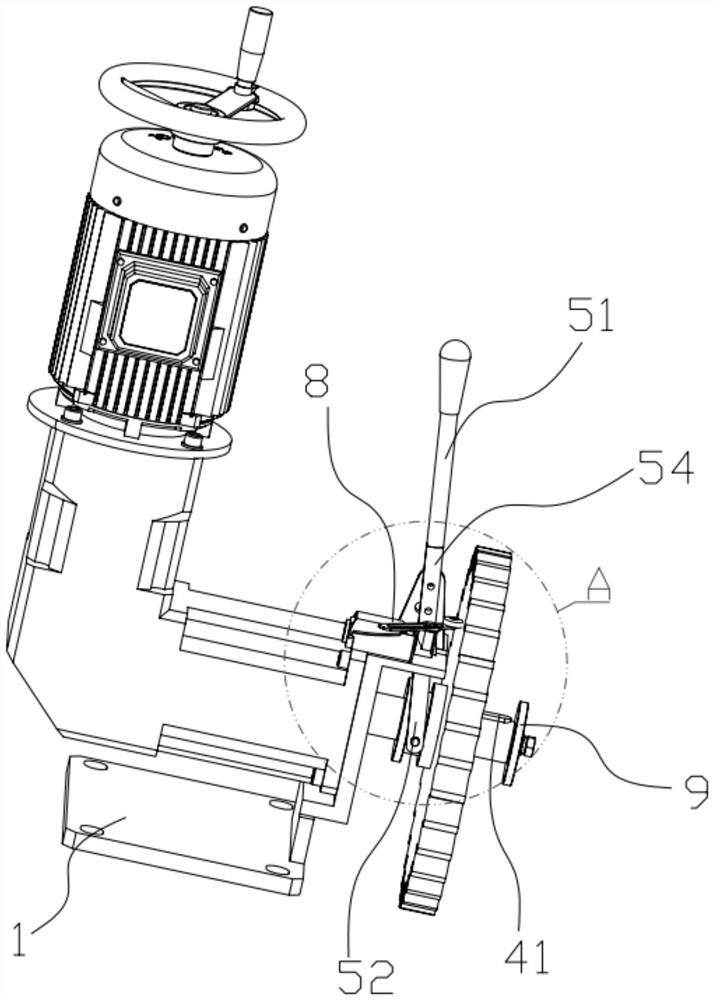
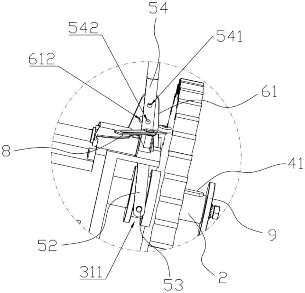
The invention discloses a turning gear. The turning gear comprises a base, a rotating shaft, a gear, a limiting assembly, a shifting fork assembly and a positioning assembly; the rotating shaft is rotatably arranged on the base; the gear is arranged on the rotating shaft in a sliding and sleeving manner; the limiting assembly is connected with the rotating shaft and the gear so as to limit the gear to rotate relative to the rotating shaft; the shifting fork assembly is rotatably arranged on the base; one end of the shifting fork assembly is rotatably connected to the gear; through rotation of the shifting fork assembly, the gear has a first state in which the gear is meshed with a flywheel of an engine and a second state in which the gear is separated from the flywheel of the engine; and the positioning assembly is connected with the base and the shifting fork assembly, so that the gear is kept in the first state or the second state. The invention provides the turning gear which solves the technical problem that an existing turning gear is not high in working efficiency.

Description

technical field [0001] The invention relates to the field of engines, in particular to a cranking device. Background technique [0002] When assembling and repairing diesel engine parts, or measuring the fuel supply advance angle and crankshaft arm distance difference, it is necessary to adjust the parts to a specific angle before assembling, disassembling or measuring, such as assembling and disassembling the connecting rod, Then the crankshaft needs to be rotated to a certain angle to have room for operation. Since the diesel engine is not started at this time, it is necessary to rotate the crankshaft through the cranking mechanism. However, the current cranking mechanism usually uses a lead screw to drive the linear motion of the driving wheel, which is complicated in structure, inconvenient to use, and affects the work efficiency of the cranking. SUMMARY OF THE INVENTION [0003] The main purpose of the present invention is to provide a cranking device, which aims to ...

Claims


Application Information

Patent Timeline
Patent Type & Authority Applications(China)
IPC IPC(8): F02B77/00
CPCF02B77/00
Inventor 邱明田
Owner 雨凡机械科技(上海)有限公司
Why Eureka
Try Eureka