Built-in anchoring balance weight detection device for rail transit overhead line system

A rail transit and detection device technology, which is applied to measuring devices, instruments, overhead lines, etc., can solve the problems of equipment hidden danger discovery and disposal lag, low efficiency, and labor-intensive inspection operations, etc.

Pending Publication Date: 2021-12-03
SHANGHAI RAIL TRANSIT MAINTENANCE SUPPORT
View PDF0 Cites 0 Cited by
  • Summary
  • Abstract
  • Description
  • Claims
  • Application Information

AI Technical Summary

Problems solved by technology

Therefore, the inspection of built-in anchors is labor-intensive and inefficient, a

Method used


Image

  • Built-in anchoring balance weight detection device for rail transit overhead line system
  • Built-in anchoring balance weight detection device for rail transit overhead line system
  • Built-in anchoring balance weight detection device for rail transit overhead line system

Examples


Embodiment Construction

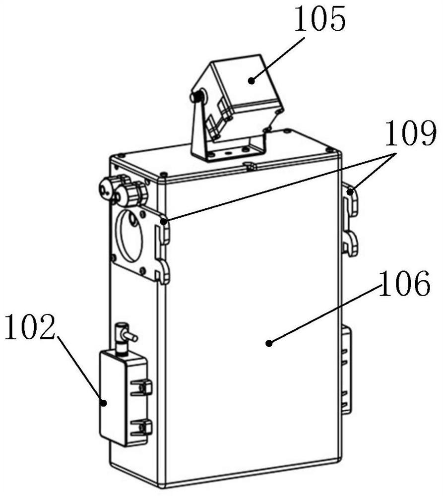
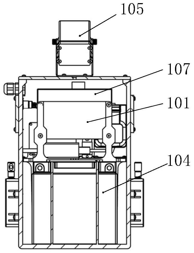
[0036] A built-in detection device for lower anchor weights in rail transit catenary provided by the present invention will be further described in detail in conjunction with the accompanying drawings and specific embodiments. The advantages and features of the present invention will become clearer from the following description. It should be noted that the drawings are in a very simplified form and all use imprecise scales, which are only used to facilitate and clearly assist the purpose of illustrating the embodiments of the present invention. In order to make the objects, features and advantages of the present invention more comprehensible, please refer to the accompanying drawings. It should be noted that the structures, proportions, sizes, etc. shown in the drawings attached to this specification are only used to match the content disclosed in the specification, for those who are familiar with this technology to understand and read, and are not used to limit the implement...


PUM


Abstract

The invention relates to a built-in anchoring balance weight detection device for a rail transit overhead line system. The built-in anchoring balance weight detection device is mainly composed of automatic monitoring equipment, a mounting mechanism and a solar power generation device. The automatic monitoring device is installed on the inner wall of the built-in anchoring hollow steel stand column through the mounting mechanism, and the solar power generation device is installed outside the steel stand column and supplies power to the automatic monitoring device. The automatic monitoring device is used for monitoring the position of the balance weight and the health state of a steel cable for hanging the balance weight; and by sensing external environment temperature and humidity value data, the recovery state of the steel cable is calculated through an algorithm. The problems that in the current maintenance technical scheme, the states of the built-in anchoring balance weight and the suspension steel cable of the built-in anchoring balance weight mainly depend on manual ladder climbing for visual inspection, the efficiency is low, and the accuracy is not high are solved.

Description

technical field [0001] The invention relates to the field of intelligent monitoring of equipment status in a rail transit power supply system, in particular to a built-in anchor drop detection device for a rail transit catenary. Background technique [0002] During the actual construction and installation of catenary built-in anchorage, due to various subjective and objective factors, the actual a and b values ​​of the compensator (a and b values ​​of the weight) are often inconsistent with the design values, such as Figure 8 As shown in (a), the a and b values ​​of the compensator refer to respectively: the distance from the end of the steel cable 403 connecting the weight 402 to the guide wheel 404 is the value a, and the distance from the lower edge of the weight to the ground is the value b. Simultaneously because steel cable 403 forms 58 ° of included angles with pendant, the wearing and tearing of steel cable 403 at guide wheel 404 position is bigger, and the phenomeno...

Claims


Application Information

Patent Timeline
IPC IPC(8): G01D21/02B60M1/26
CPCG01D21/02B60M1/26
Inventor 高威军唐志强卞建峰郑缘卿姜庆徐春华李想过俊徐仁懿黄介坤杨天炜朱佳栋徐豪石云嘉
Owner SHANGHAI RAIL TRANSIT MAINTENANCE SUPPORT
Why Eureka
Try Eureka