Rotary driving telescopic mechanism

A technology of telescopic mechanism and rotary drive, which is applied in the direction of assembly machines, electrical components, electric switches, etc., to achieve the effects of avoiding assembly wear, convenient operation, and high assembly efficiency

Active Publication Date: 2021-12-03
CHINA AIR TO AIR MISSILE INST
View PDF12 Cites 1 Cited by
  • Summary
  • Abstract
  • Description
  • Claims
  • Application Information

AI Technical Summary

Problems solved by technology

[0002] The control system usually uses a micro switch as the actuator for key state signal collection and switching. In order to drive the micro switch for state switching, a mechanism that can convert rotary motion into linear motion is needed, and the micro switch roller is pressed to achieve it; In addition, it is also necessary for the mechanism to be simple and small, easy to manufacture, assemble, replace and maintain, low in production cost, stable in execution, high in execution accuracy, and high in service life. Since there is no corresponding mechanism that can meet the use requirements, Therefore, a redesign is required

Method used


Image

  • Rotary driving telescopic mechanism
  • Rotary driving telescopic mechanism
  • Rotary driving telescopic mechanism

Examples


Embodiment Construction

[0027] The technical solutions of the present invention will be described below in conjunction with the accompanying drawings in the embodiments of the present invention. In the description, it should be understood ", "Right" and other indicated orientations or positional relationships are only corresponding to the drawings of the present invention. In order to facilitate the description of the present invention, they do not indicate or imply that the referred device or element must have a specific orientation:

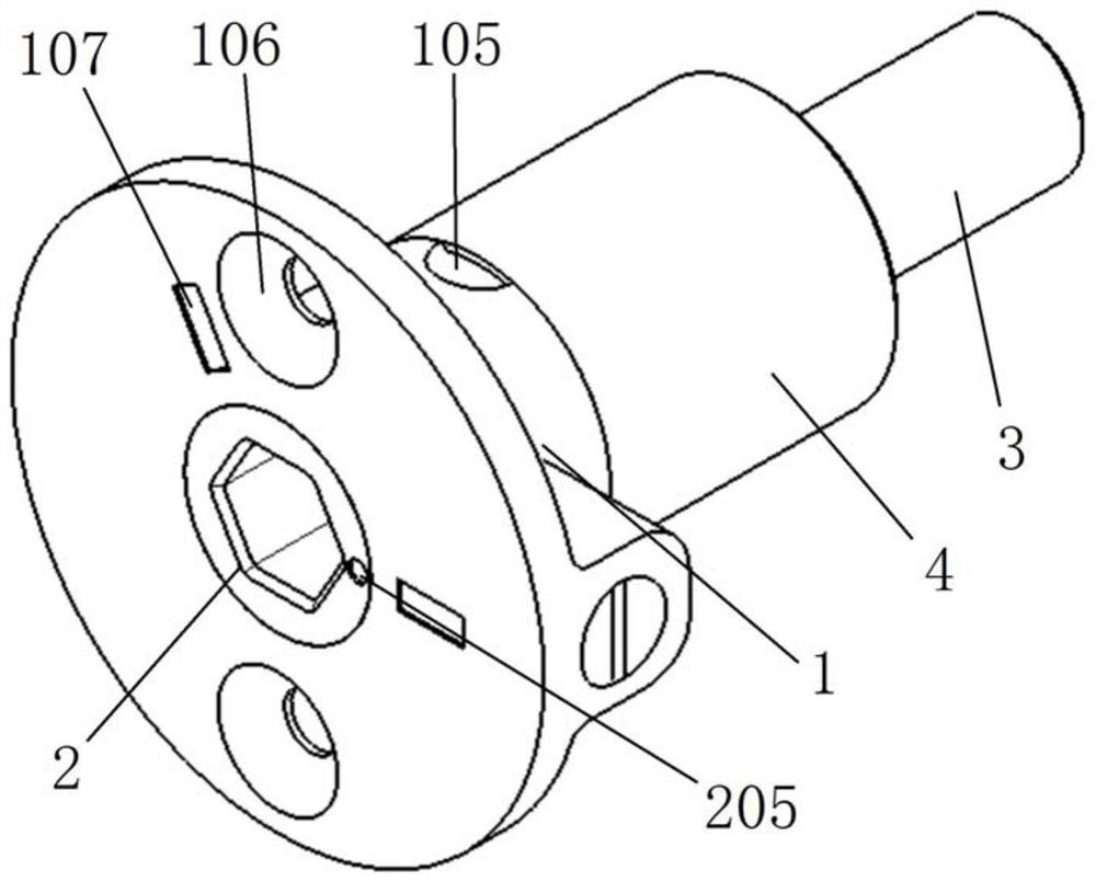
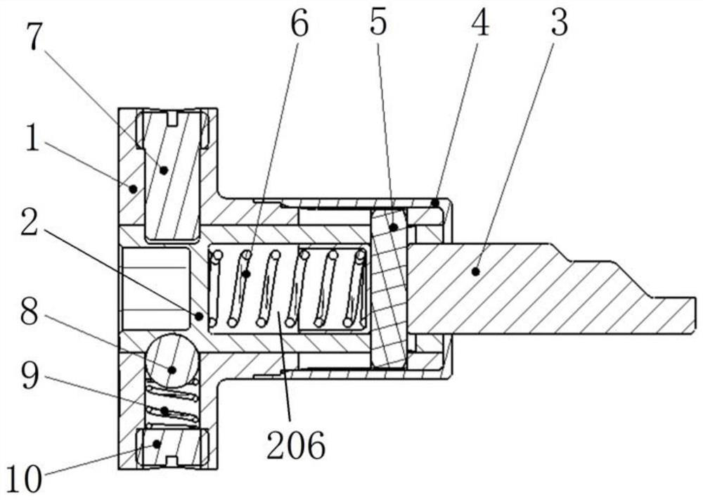
[0028] combined with Figure 1-7 The rotation-driven telescopic mechanism includes a flange sleeve 1, a rotating rod 2, a telescopic rod 3, a protective sleeve 4, a positioning pin 5, a screw head pin shaft 7 and a set screw plug 10;

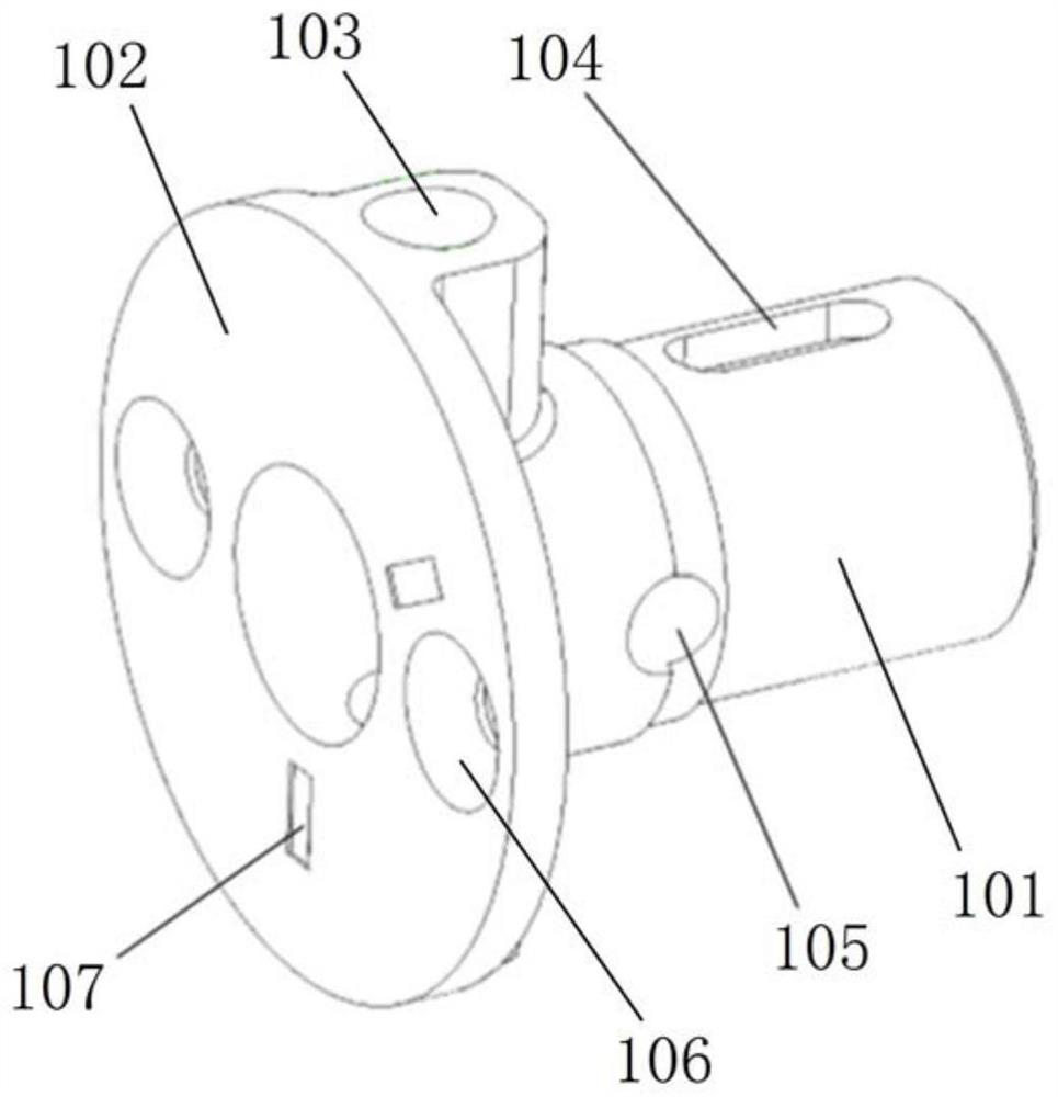
[0029] The flange sleeve 1 includes a casing 101 adapted to rotate and insert the rotating rod 2, and a flange 102 integrally arranged on the outer wall of one end of the casing 101. The casing 101 is used to radially position the rotat...


PUM


Abstract

The invention relates to a rotation driving telescopic mechanism in the technical field of driving mechanism design. The rotary driving telescopic mechanism comprises a flange sleeve, a rotating rod, a telescopic rod, a protective sleeve, a positioning pin, a screw head pin shaft and a fastening screwed plug, the flange sleeve comprises a sleeve shell and a flange plate, two countersunk head through holes are formed in the outer wall of the flange sleeve, a screw head pin shaft and a fastening screwed plug are arranged in the two countersunk head through holes respectively, a positioning spring and a positioning ball are sequentially arranged at the inner end of the fastening screwed plug, and two kidney-shaped holes are formed in the shell wall of the other end of the sleeve shell; an inner square hole is formed in one end face of the rotating rod, a first center hole is formed in the other end face of the rotating rod, and a groove, two limiting ball sockets and two spiral grooves are formed in the outer wall of the rotating rod; a second center hole is formed in the telescopic rod, a compression spring is arranged between the first center hole and the second center hole, and a pin hole is formed in a rod body of the telescopic rod; the protective sleeve comprises a sleeve and a sealing head plate; a through hole is formed in the center of the sealing head plate; and the telescopic mechanism is convenient to operate, accurate in positioning, compact in structure, high in reliability and capable of meeting the wide requirements of manufacturing and using.

Description

technical field [0001] The invention relates to the technical field of driving mechanism design, in particular to a rotation-driven telescopic mechanism. Background technique [0002] The control system usually uses a micro switch as the actuator for key state signal acquisition and switching. In order to drive the micro switch for state switching, a mechanism that can convert rotational motion into linear motion is needed, and the micro switch roller is pressed to achieve it; In addition, it is also necessary for the mechanism to be simple and small, easy to manufacture, assemble, replace and maintain, low in production cost, stable in execution, high in execution accuracy, and high in service life. Since there is no corresponding mechanism that can meet the use requirements, Therefore, a redesign is required. Contents of the invention [0003] In order to overcome the deficiencies in the background technology, the present invention discloses a rotation-driven telescopic...

Claims


Application Information

Patent Timeline
Patent Type & Authority Applications(China)
IPC IPC(8): H01H13/20B23P21/00
CPCH01H13/20B23P21/00Y02E10/50
Inventor 陈晖景凤理单奇异蔺绍玲李世争李海春
Owner CHINA AIR TO AIR MISSILE INST
Why Eureka
Try Eureka