
Chain type stator core and motor

A stator core and chain technology, applied in electrical components, electromechanical devices, electric components, etc., can solve the problems of small lamination spacing and difficult rotation of the stator core, and achieve the effect of increasing the lamination coefficient

Active Publication Date: 2021-12-03
ZHUHAI GREE REFRIGERATION TECH CENT OF ENERGY SAVING & ENVIRONMENTAL PROTECTION
View PDF3 Cites 0 Cited by
  • Summary
  • Abstract
  • Description
  • Claims
  • Application Information

AI Technical Summary

Problems solved by technology

[0003] In view of this, the present invention discloses a chain-type stator core and a motor, which are used to solve the The distance between the core stacks is too small, causing difficult rotation problems

Method used


Image

  • Chain type stator core and motor
  • Chain type stator core and motor
  • Chain type stator core and motor

Examples


Embodiment 1

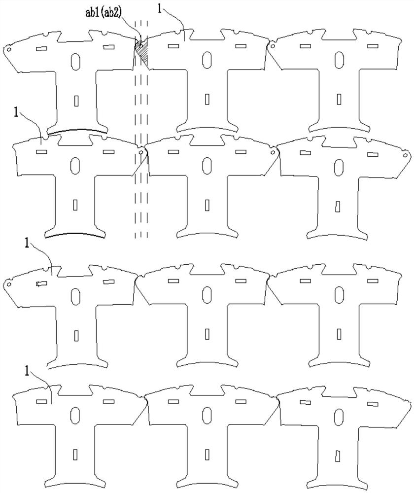
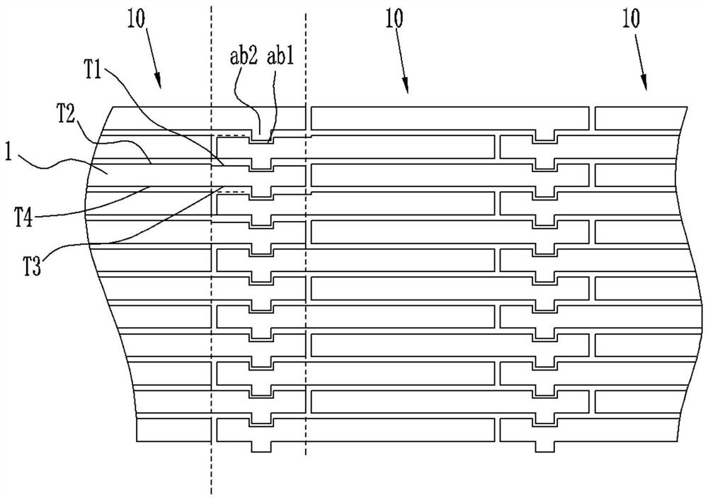
[0034] In this embodiment, a chain stator core is provided, such as figure 2 and image 3 As shown, it includes several stator core units 10, any one of the stator core units 10 is formed by lamination of several stator core laminations 1, and the stator cores of two adjacent stator core units 10 are stacked The pieces 1 are rotated and fastened together to form a stator core chain, and the two ends of the stator core chain are fixedly connected to form the chain stator core, and the rotation connections of the two mutually rotating and fastened stator core laminations 1 The spacing between regions is greater than the spacing between non-rotatingly connected overlapping regions.

[0035] As a preferred implementation manner of this embodiment, the thickness of the overlap area of ​​rotation connection on any of the stator core laminations 1 is smaller than the thickness of the non-rotation connection overlap area of ​​the stator core lamination 1 itself.

[0036] like figu...

Embodiment 2

[0047] In this embodiment, a chain stator core is provided, such as Figure 8 As shown, it includes several stator core units 10, any one of the stator core units 10 is formed by lamination of several stator core laminations 1, and the laminations of two adjacent stator core units 10 rotate with each other Buckled together to form a stator core chain, the two ends of the stator core chain are fixedly connected to form the chain-type stator core, and the stator core laminations 1 on any one of the stator core units 10 are divided into the first group and the second group, the stator core laminations of the first group are distributed on both sides in the thickness direction of the stator core laminations 1 of the second group, and the first two adjacent stator core units 10 The sets of stator core laminations 1 are rotated and fastened together, and only the end edges of the second set of stator core laminations 1 on two adjacent stator core units 10 cooperate with each other. ...

Embodiment 3

[0059] In this embodiment, a motor is provided, including the chain stator core described in Embodiment 1 or 2.


PUM


Abstract

The invention discloses a chain type stator core and a motor, which are used for solving the problem that when a lamination coefficient of a stator core is relatively large, the space between stator core laminations of each layer is too small, so that the rotation is difficult. The chain type stator core comprises a plurality of stator core units, wherein an arbitrary stator core unit is formed by laminating a plurality of stator core laminations, the stator core laminations of two adjacent stator core units are mutually rotated and buckled together to form a stator core chain, the two ends of the stator core chain are fixedly connected to form the chain type stator core, and the distance between the rotating connection overlapping areas of the two stator core laminations which are mutually and rotatably buckled is larger than the distance between the non-rotating connection overlapping areas of the two stator core laminations which are mutually and rotatably buckled. According to the chain type stator core, the thickness of the rotating connection overlapping areas of the stator core laminations is smaller than that of the non-rotating connection overlapping areas, so that the problem that two adjacent stator core units cannot rotate relatively due to overlarge extrusion force is solved; and meanwhile, the lamination coefficient of the stator iron core is further increased.

Description

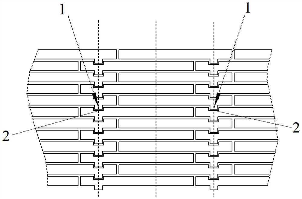
technical field [0001] The invention relates to the technical field of motors, in particular to a chain-type stator core and a motor. Background technique [0002] like figure 1 As shown in the figure, the chain-type motor rotates hingedly through the convex joint 1 and the concave joint 2 between the stator core units, so that the space for inserting wires at the stator teeth becomes larger. Compared with the conventional motor with an integral stator core, it can greatly Improve the slot full rate of the motor, thereby improving the efficiency of the motor. However, due to the rotation of the convex joint 1 and the concave joint 2, the lamination coefficient of the axially laminated stator core is limited. If the distance between them is too small, it will be difficult to rotate. Contents of the invention [0003] In view of this, the present invention discloses a chain-type stator core and a motor, which are used to solve the problem of difficult rotation caused by t...

Claims


Application Information

Patent Timeline
Patent Type & Authority Applications(China)
IPC IPC(8): H02K1/14H02K1/18
CPCH02K1/148H02K1/185H02K2213/03
Inventor 张辉周博于潇逍
Owner ZHUHAI GREE REFRIGERATION TECH CENT OF ENERGY SAVING & ENVIRONMENTAL PROTECTION
Learn More