
Rotor manufacturing apparatus

A technology for manufacturing devices and rotors, applied in electromechanical devices, manufacturing motor generators, manufacturing stator/rotor bodies, etc., can solve problems such as inability to supply resin, and achieve the effect of easy positioning

Pending Publication Date: 2021-12-03
NIPPON DENSAN CORP
View PDF1 Cites 0 Cited by
  • Summary
  • Abstract
  • Description
  • Claims
  • Application Information

AI Technical Summary

Problems solved by technology

Therefore, there is a possibility that the resin cannot be supplied into the magnet insertion hole.

Method used


Image

  • Rotor manufacturing apparatus
  • Rotor manufacturing apparatus
  • Rotor manufacturing apparatus

Examples


Embodiment Construction

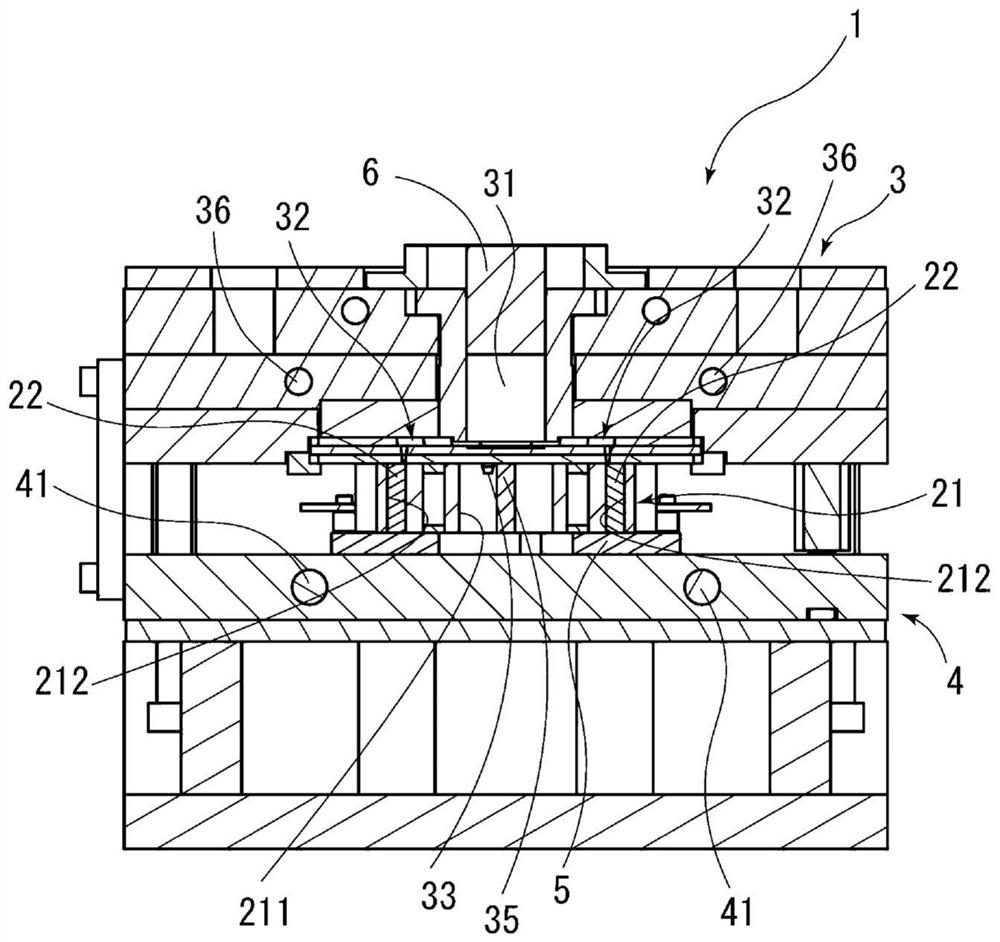
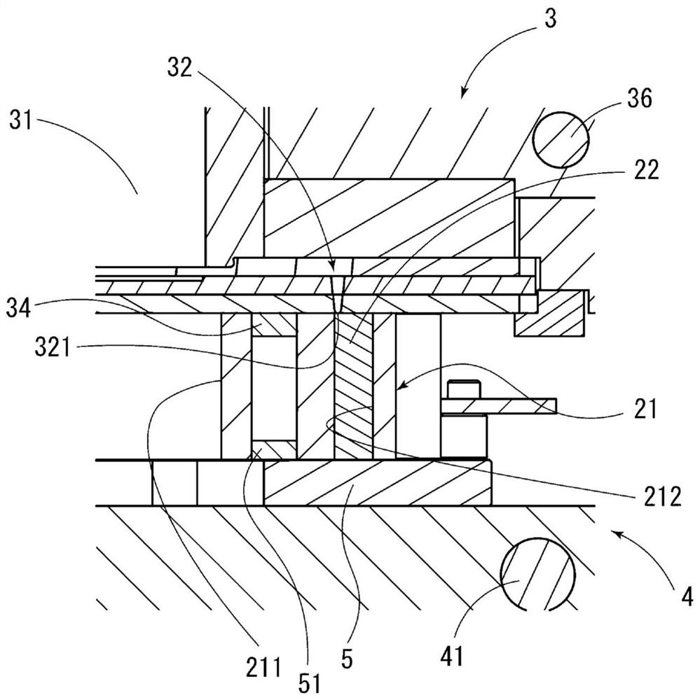
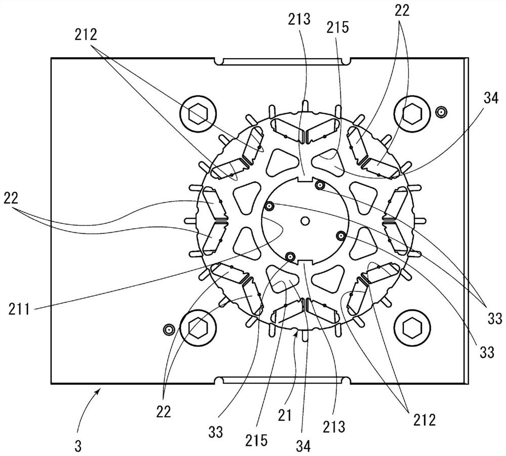
[0019] Hereinafter, embodiments of the present invention will be described in detail with reference to the drawings. In addition, the same code|symbol is attached|subjected to the same or corresponding part in a figure, and the description is not repeated here. In addition, the dimensions of the components in the drawings do not faithfully represent the dimensions of the actual components, the dimensional ratios of the components, and the like.

[0020] In addition, below, in the description of the rotor manufacturing apparatus 1, the direction parallel to the axis of the rotor main body 21 is referred to as the "axial direction", the direction perpendicular to the axis is referred to as the "radial direction", and the direction along the axis is referred to as "radial". The direction of the arc at the center is called "circumferential". In addition, let the vertical direction in the state where the rotor manufacturing apparatus 1 is installed be a "up-down direction". Howev...


PUM


Abstract

The invention provides a rotor manufacturing apparatus for manufacturing a rotor having an accommodation hole for accommodating a magnet, the rotor manufacturing apparatus being capable of easily positioning a rotor main body in supplying a resin into the accommodation hole. A rotor manufacturing apparatus (1) is a rotor manufacturing apparatus for manufacturing a rotor including a rotor main body (21) having a hole (211) located at its center and an accommodation hole (212) accommodating a magnet (22) and the magnet (22) accommodated in the accommodation hole (212) and fixed in the accommodation hole (212) with a resin. The rotor manufacturing apparatus (1) includes: a first mold (3) including a resin receive space portion (31) receiving the resin to be supplied into the accommodation hole, a flow path (32) through which the molten resin flows into the accommodation hole, and a contact portion (33) inserted in the hole, the contact portion (33) being in contact with an inner peripheral face of the hole; and a second mold (4) configured to sandwich the rotor main body (21) in conjunction with the first mold.

Description

technical field [0001] The present invention relates to a rotor manufacturing device. Background technique [0002] There is known an apparatus for manufacturing a rotor in which permanent magnets are fixed with resin in magnet insertion holes of a laminate. For example, Patent Document 1 discloses a resin filling device including a pair of holding members and a filling machine as a manufacturing device of a laminated iron core. [0003] In the resin filling device of the above-mentioned Patent Document 1, the pair of clamping members are rectangular flat plates arranged side by side in the vertical direction. Among the pair of holding members, the holding member located on the upper side has a plurality of resin flow paths penetrating in the thickness direction. Filling machines have multiple rams and drives. The plurality of plungers are located one by one in each resin flow path, and are movable in each resin flow path. The drive mechanism is an air cylinder or the li...

Claims


Application Information

Patent Timeline
Patent Type & Authority Applications(China)
IPC IPC(8): H02K15/03
CPCH02K15/03B29C39/10B29C39/26B29C39/24B29C39/38B29C33/303B29C33/301B29C45/14778B29K2105/203B29C45/14344B29C2045/2717B29C45/27B29C2045/14934B29L2031/34H02K15/12H02K1/2766B29L2031/7498B29C45/02
Inventor 竹中彰岩田浩一辻英希田中阳介
Owner NIPPON DENSAN CORP
Learn More