
Landfilling pool for hazardous solid waste

A technology for hazardous solids and wastes, which can be used in the removal of solid wastes, grain processing, etc., and can solve the problems of inaccessibility and aggregation of solid wastes.

Pending Publication Date: 2021-12-07
吴丽秋
View PDF7 Cites 0 Cited by
  • Summary
  • Abstract
  • Description
  • Claims
  • Application Information

AI Technical Summary

Problems solved by technology

[0003] Based on the above description, the inventors found that the existing landfill pond for hazardous solid waste mainly has the following disadvantages, for example: after the waste residue in the landfill pond reacts, high-temperature heat will be formed to convert the solid in the landfill pond into liquid , the liquid gradually increases, causing the air pressure to float up and squeeze the conveying pipe, so that the conveying pipe will be squeezed with the internal poisonous gas when conveying piles of solid waste, resulting in part of the solid waste being squeezed by the gas and unable to enter the landfill pool. Reaction treatment, resulting in the accumulation of waste slag in the pipeline to form agglomeration

Method used


Image

  • Landfilling pool for hazardous solid waste
  • Landfilling pool for hazardous solid waste
  • Landfilling pool for hazardous solid waste

Examples


Embodiment 1

[0030] as attached figure 1 to attach Figure 6 Shown:

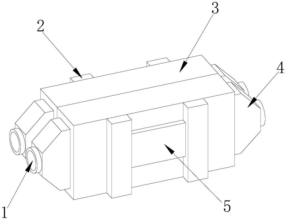
[0031] The present invention provides a landfill pool for hazardous solid waste, the structure of which includes a conveying pipe 1, a fixing frame 2, a transmission box 3, a connecting box 4, and a fixing plate 5, and the inner side of the conveying pipe 1 is welded and connected to the outer side of the connecting box 4 The inner side of the fixed frame 2 is fixedly connected to the outer side of the transmission box 3, the outer side of the transmission box 3 is connected to the inner side of the connection box 4 by studs, and the outer side of the fixed plate 5 is riveted connected to the inner side of the fixed frame 2.

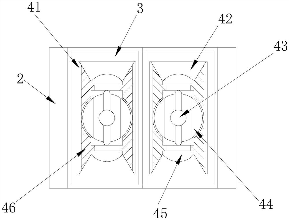
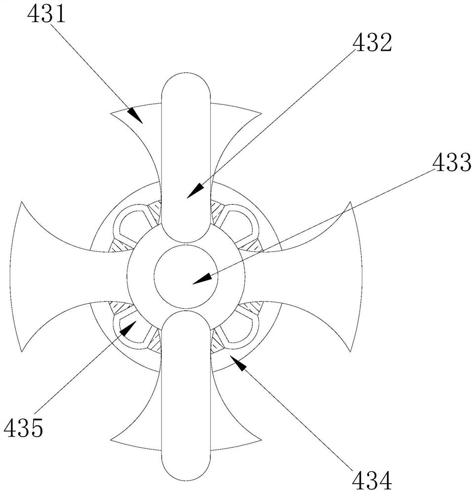
[0032] Wherein, the connection box 4 is provided with a support frame 41, a splint 42, a cutting device 43, a scraping device 44, a connecting column 45, and a support plate 46, the inside of the support frame 41 is fixed to the outside of the splint 42, and the splint 42 is riveted with the oute...

Embodiment 2

[0040] as attached Figure 7 To attach Figure 9 Shown:

[0041] The present invention provides a landfill pool for hazardous solid waste. The scraper 44 is provided with a scraper 441, a connecting ring 442, a clamp 443, a clamping rod 444, and a connecting plate 445. The outer side of the scraper 441 is welded. Connected to the inner side of the connecting plate 445, the outer side of the connecting ring 442 is attached to the inner side of the clamping rod 444, the rear end of the clamp 443 is fixed to the front end of the connecting plate 445, and the outer side of the clamping rod 444 is embedded and fixed on the inner side of the scraper 441 , the four clamping rods 444 are arranged vertically and symmetrically, so that the scraper 441 can be kept stable after being in contact with the cutting device 43 .

[0042] Wherein, the scraper 441 is provided with a scraper c1, a clamping block c2, a telescopic column c3, a connecting frame c4, and a top frame c5, the outside o...


PUM


Abstract

The invention discloses a landfilling pool for hazardous solid waste. The landfilling pool structurally comprises a conveying pipe, a fixing frame, a transmission box, a connecting box and a fixing plate; the inner side of the conveying pipe is connected in a welded mode to the outer side of the connecting box; the inner side of the fixing frame is fixedly connected to the outer side of the transmission box; the outer side of the transmission box is connected to the inner side of the connecting box through a stud; the outer side of the fixing plate is connected in a riveted mode to the inner side of the fixing frame; the waste enters the conveying pipe, the conveying pipe enters the inner side of a scraping device to carry out conveying, a rotating column on the inner side of a supporting frame rotates, a pressing block is clung to the front ends of an abutting plate and an ejecting block, then a clamping block pushes a clamping strip to abut against an ejecting plate, the ejecting plate carries out squeezing and shrinking on an abutting ring and a connecting rod outside a clamping plate, and an elastic strip rebounds to cut the solid waste into fragments to convey into the transmission box for reaction, thereby preventing the phenomenon that the waste cannot enter the inner side of the scraping device in a blocking form, resulting in that part of solid waste residues cannot enter the landfilling pool for reaction treatment due to gas extrusion, and the waste residues are accumulated in a conveying pipeline to form gathering.

Description

technical field [0001] The invention belongs to the technical field of hazardous solid waste disposal, and in particular relates to a landfill pool for hazardous solid waste. Background technique [0002] Hazardous solid waste is a kind of toxic waste residue. The waste residue is transported from the pipeline of the waste pond to the landfill pond, and put into the soil pit for soil covering, so that the toxic gas generated after the reaction between the waste residue and the reaction solution is not exposed to the air. conduct harm. [0003] Based on the above description, the inventors found that the existing landfill pond for hazardous solid waste mainly has the following disadvantages, for example: after the waste residue in the landfill pond reacts, high-temperature heat will be formed to convert the solid in the landfill pond into liquid , the liquid gradually increases, causing the air pressure to float up and squeeze the conveying pipe, so that the conveying pipe w...

Claims


Application Information

Patent Timeline
Patent Type & Authority Applications(China)
IPC IPC(8): B09B1/00B09B3/00B09B5/00B02C18/14B02C18/18
CPCB09B1/00B09B3/00B09B5/00B02C18/142B02C18/18
Inventor 吴丽秋
Owner 吴丽秋
Learn More