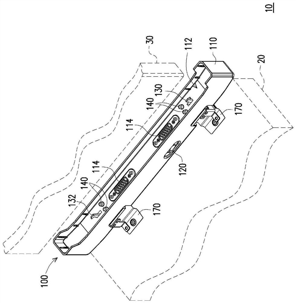
[0062] figure 1 It is a partial schematic view of a portable electronic device according to one embodiment of the present invention. See figure 1 In the present embodiment, the portable electronic device 10 includes a lower body 20, a slot structure 100 and an upper body 30. Slot structure 100 connected to the lower body 20, the body 30 is detachably disposed in the slot structure 100. The upper body 30, for example, a tablet or other electronic device handset. Comprises a slot structure 100 exposed in the recess 114 of the electrical connector 112, adapted to be electrically connected to the 30 disposed within a groove 112 on the body. Further, the slot structure 100 includes a housing 110 in a hinge assembly 170, 170 adapted to the hinge assembly 20 connected to the lower body, so that the socket structure 100 can be rotated with respect to the keyboard module, the slot structure 100 is mounted to the body 30 can be changed with respect to the angle of the keyboard module. Of course, the application of the slot structure 100 is not limited thereto.
[0063] In the present embodiment, the slot structure 100 may be used to comprise the body 30 is stably fixed to the internal structure of the groove 112, as will be described below.
[0064] figure 2 Yes figure 1 The slot structure of the switch in the schematic front view of a fixed bit position. image 3 Yes figure 1 Switch bit slot structure in a schematic front view of an unlocked position. It is noted that, in order to clearly see the internal structure of the housing 110 shown in phantom. See figure 2 and image 3In the present embodiment, the slot structure 100 includes a housing 110, a switch 120, a first hook 132 and second hook 130 a. Switch 120 and exposed movably disposed in the housing 110. A first hook 132 and second hook 130 is exposed in the recess 112, and the first hook 132 and second hook 130 adapted for engaging the body 30 or disengaged.
[0065] In the present embodiment, the first hook 132 and second hook 130 reversely arranged, the first hook 132 in the same direction of movement of the switch 120 to the switch 120 interlocking manner, with the second hook 130 the opposite direction moves the switch 120 to the switch 120 interlocked manner. So, if image 3 , When the switch 120 is moved along the first direction D1, the first hook 132 corresponding to the first direction D1, the second hook 130 moves in the second direction D2, which is opposite to the first direction D1 the second direction D2.
[0066] Thus, the slot structure 100 of the present invention will be able to single switch 120 to control movement of the first locking hook 132 and the reverse second hook 130, not only can be easily operated by the user, it is possible to provide two-way fixed, and enhance the fixation effect. Specifically, for example, when the tablet body 30 into the slot 100 of the groove structure 112, a first hook 132 and second hook 130 can be inserted into the two holes 30 corresponding to the body, and may be as Figure 3 to 2 Actuation, a first hook 132 and second hook 130 to move to the side to the fixing position P1, the first hook 132 and second hook 130 engaging the upper body 30, so that the body 30 not easily coming out of the slot structure 100 in groove 112. When the upper body 30 to the slot structure 100 clears the notch 112, may be as Figures 2 to 3 Actuation, moves the switch 120, the first hook 132 and second hook 130 moves inward to the unlocked position P2.
[0067] Further, the slot structure 100 further comprises two resilient members 150, wherein the resilient member 150 is connected to a structure on the housing 110 (shown in phantom) reversed to the first direction D1 between the first 132 and the hook ( the second direction D2) providing a resilient force, the resilient member 150 is connected to other structures on the housing 110 (shown in phantom) along a first direction D1 to provide an elastic force between 130 and second hook. Two elastic members 150 to the first hook 132 and second hook 130 return, so that when the body 30 is inserted into the slot structure 100, a first hook 132 and second hook 130 fixed to the sides of the mobile when the position P1, the user will need to manually control the switch 120 so that the first hook 132 and second hook 130 return, the operation is very convenient.
[0068] First will be described the interlocking relationship between the first hook 132 and the switch 120. Figure 4 It is hidden figure 1 A schematic configuration of a slot. Figure 5A Yes Figure 4 Local enlargement. Figure 5B Yes Figure 5A The other view. Figure 6A Yes Figure 5A The first hook is a schematic view of the unlocked position is located. Figure 6B Yes Figure 6A The other view. It is noted that, in order to show the internal structure, the housing 110 is hidden, the resilient member 150 at one end of Figures 4 to 6B Although not connected to the structure, it would in fact be connected to the housing 110 to be hidden.
[0069] See Figures 4 to 6B In the present embodiment, the slot structure 100 includes a linkage member 125. The interlocking member 125 is located within the housing 110 and is linked to the switch 120. A first hook 132 connected to the movable member 125 interlocked. Specifically, in the present embodiment, the interlocking member 125 includes an opening 127, a first hook 132 having an opening 131 in a plate 127 extending, extension plates 131 against the movable member 125 in succession. Thus, even when the movable member 125 moves directly push the bottom plate 131 extends, the first hook 132 to move along the same.
[0070] Further, in order that the first hook 132 can be stably moved along the first direction D1, without sideways deflection, in the present embodiment, the slot structure 100 further comprises a first and a second guide plate 135 card 135 is connected to a first guide block 136, a first hook guide plate 132, a first guide plate 135 having a first guide groove 134, a first guide groove 134 extending along a first direction Dl, the first guide block 136 fixed to the housing 110 and extends into the first guide groove 134. This design allows the first hook 132 can be stably moved along a single axis, fails to avoid shaking oriented engaging body 30.
[0071] Next will be described a second hook 130 and the switch 120 how one can achieve a reverse interlocking. Figures 7A to 7C Yes Figure 4 A second hook positioned at different viewing angles partial enlarged schematic view of a fixed position. Figures 8A to 8C Yes Figure 4 When the different perspectives of the second hook in the unlocked position of the partial enlarged view. It is noted that, in order to show the internal structure, the housing 110 is hidden, the resilient member 150 at one end of Figures 7A to 8C Although not connected to the structure, it would in fact be connected to the housing 110 to be hidden.
[0072] See Figures 7A to 8C , The slot structure 100 of the present embodiment further includes a gear 160 and a rotating arm 165. The interlocking member 125 has a rack 126 on the inside. Gear 160 and is engaged with the rack 126 positioned within the housing 110. Arm 165 is pivotally positioned within the housing 110 and is connected to one end of the stud 160 of the gear 162, the other end of the movable arm 165 is connected to the second hook 130. In the present embodiment, the other end of the arm 165, for example, 166 is fixed to the second locking hook 130. In other embodiments, the other end of the arm 165 may also be a second hook 130 integrally.
[0073] When the switch 120 ( image 3 ) Is moved in a first direction D1, corresponding to the interlocking member 125 moves in the first direction D1, with the rack gear 160 moves the interlocking member 125 is rotated 126, as driven by the arm 165 Figures 7A to 8A The substantially opposite to the direction of movement, the second hook 130 backward toward the first direction D1 (second direction D2) movement.
[0074] Similarly, the second hook 130 in order to make possible to stably move the second direction D2, and not sideways deflection, in the present embodiment, the slot structure 100 further comprises a second guide plate 137 ( Figure 7C ) And a second guide block 139 ( Figure 7C ), Second guide plate 137 is connected to the second hook 130, the second guide plate 137 has a second guide groove 138, second guide groove 138 extending along a second direction D2 of the second guide block 139 is fixed to the It extends into the housing 110 and the second guide groove 138. Thus, even if the arm 165 is not completely moved along a second direction D2, the second hook 130 can be stably moved along a single axis, fails to avoid shaking oriented engaging body 30.
[0075] Further, the second hook 130 has a bottom plate 131 extends, the slot structure 100 further includes a spring pin 140, the groove 112 and 131 respectively against the extension plates. Pogo pin 140 is vertically movably disposed in the housing 110. When the spring 140 is on the needle body 30 in a vertical direction D 3 When the pressure inside the pogo pin 140 is a compression spring, the latch spring 142 of pin 140 will abut against the base plate 131 extends.
[0076] by Figure 7C and Figure 8C For example, the base plate 131 having a hole extending 133, when the pogo pin 140 in a direction perpendicular to the second direction D 2 Perpendicular to direction D 3 Is depressed position and the second hook 130 from the fixed position P1 to the unlocked position P2, the base plate 131 extends relative movement of the spring pins 140, the holes 133 corresponding to the spring to move the needle 140. At this time, the spring pins 140 to release the internal spring, the spring latch pin 140 can extend into the holes 142 of 133, the extension plates 131 are temporarily fixed, the second hook 130 is temporarily fixed.
[0077] Similarly, if Figure 5B and Figure 6B , When the pogo pin 140 in a direction perpendicular to the first direction D 1 Perpendicular to direction D 3 Is pressed and the first hook 132 from the fixed position P1 to the unlocked position P2, the base plate 131 extends relative movement of the pogo pin 140, the hole 133 is moved to a position corresponding to the spring 140 of the needle. At this time, the spring pins 140 to release the internal spring, the spring latch pin 140 can extend into the holes 142 of 133, the extension plates 131 are temporarily fixed, the first hook 132 is fixed temporarily.
[0078] In the present embodiment, when the second hook 130 in a fixed position P1, the resilient member 150 has not been stretched, when the user moves the switch 120, the second hook 130 is fixed by the position P1 to the unlocked position P2, the elastic member 150 is elongated accumulate an elastic potential energy. In this state, the spring pin extends into the bolt holes 142,140 of 133, the elastic member 150 is temporarily fixed in the elongated state. Thus, the second hook 130 can stay in the unlocked position P2. Similarly, in the present embodiment, the first hook 132 also has a bottom plate 131 and extending the corresponding spring pins 140 and the elastic member 150 to the first hook 132 can stay in the unlocked position P2.
[0079] Thus, when the user switch 120 is left from the first direction D1 ( figure 2 ) Moved to the right ( image 3 ), The first hook 132 and second hook 130 can stay in the unlocked position P2, so that the switch 120 is fixed to the image 3 Position (right), a user need not continuously urging the switch 120 is maintained at image 3 s position. This design greatly increases the ease of use.
[0080] Thereafter, when the user clears the notch 112 on the body 30, the spring pin 140 is no longer pressed, spring pins 140 can move integrally, the pin 142 extending away from the base plate aperture 131, 133, and 132 of the first hook two hooks 130 can be pulled by two elastic members 150 and return.
[0081] Specifically, when the two spring pins 140 in a vertical direction D 3 When the reverse movement upward, two spring pins 140 extending away from the base plate 131, two two holes 133, the first hook 132 and second hook 130 are not subject to binding. In this case, near the second hook 150 of the elastic member 130 elastic potential energy is released, the second hook 130 moves toward the first direction D1. Further, near the first hook 150 of the elastic member 132 elastic potential energy is released, the first hook 132 in the second direction D 2 Movement, so that the first hook 132 and second hook 130 is fixed by the position P1 to the unlocking position P2. In this process, the gear 160 with the movement of the arm 165 is rotated to drive the rack 126 is moved, the interlocking member 125 moves the switch 120 back into place.
[0082] It is worth mentioning that, in the present embodiment, the slot structure 100 in a fixed position P1 is a normal state, in other embodiments, the slot structure may be when the first hook 132 and second hook 130 is located fixed position P1, two elastic members 150 is elongated, and the spring latch pins 142,140 extend into holes 133 in the design, such that the slot in the unlocked position P2 under normal structure 100, the slot structure is not designed to be attached The picture shows the limit.
[0083]In summary, the switch of the slot structure of the present invention is connected to the first check by the functions, and the first lock hook can be moved with the switch.Further, the switch engages the rack of the rack by the rack on the connector, pivoting the second card hook, and moving the second card hook in reverse movement with the switch.In this way, the slot structure of the present invention can control the first check and second card hook of the reverse motion in a single switch, not only can convenient user operation, but also provide two-way fixing, and increase the fixing effect.Furthermore, by the setting of the slot structure, the user can take a single hand to remove or assemble the upper body, and do not need to press or operate any elements during the process of removing the upper body.Furthermore, when the upper body is removed, the first check and the second card are automatically reply to the fixed position, and the upper body can be inserted into the slot structure when assembled next time.The convenience of use can be increased via a single-hand mode of operation.