Eureka AIR delivers breakthrough ideas for toughest innovation challenges, trusted by R&D personnel around the world.

Timestamp determination method and related equipment

A time stamp determination and time stamp technology, applied in time division multiplexing systems, electrical components, multiplex communication, etc., can solve the problems of different time stamps, inaccurate time stamps, and inability to guarantee time stamps, etc.

Active Publication Date: 2021-12-07
HANGZHOU HIKVISION DIGITAL TECH
View PDF6 Cites 2 Cited by
  • Summary
  • Abstract
  • Description
  • Claims
  • Application Information

AI Technical Summary

Problems solved by technology

[0004] Obviously, the time stamp of the above determined IMU data is delayed relative to the time point when the IMU data is actually collected, and the time stamp of the determined image data is also delayed relative to the time point when the image data is actually collected, so that the determined time stamp is not very accurate
And in the above method, the time stamp of the IMU data and the time stamp of the image data are determined independently, and it cannot be guaranteed that the time stamp of the IMU data and the time stamp of the image data are determined under the same clock system, resulting in actually the same time The collected IMU data and image data, but the time stamps of the two are not the same (that is, the time stamps of the two are not synchronized), which affects the accuracy of subsequent determination of pose information based on IMU data and image data

Method used

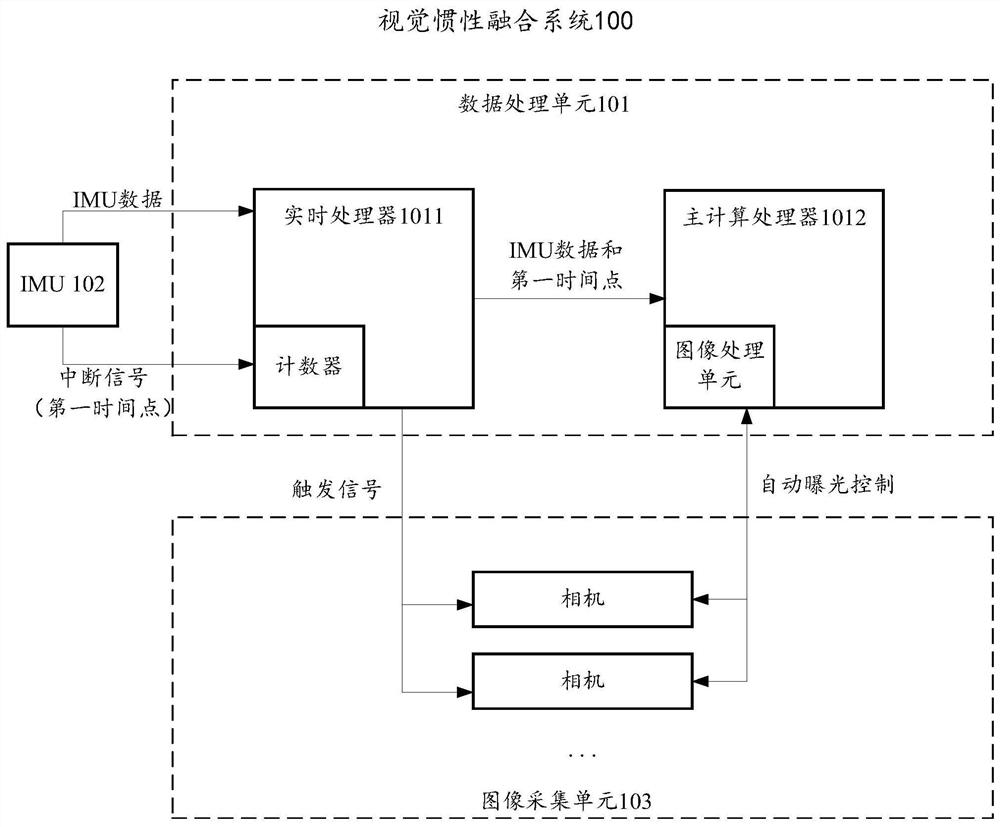
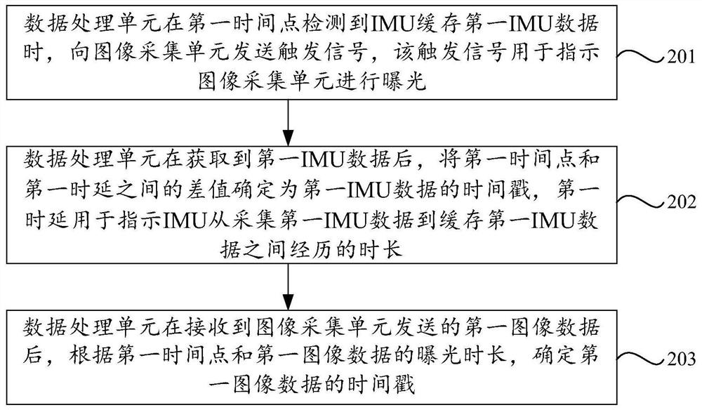
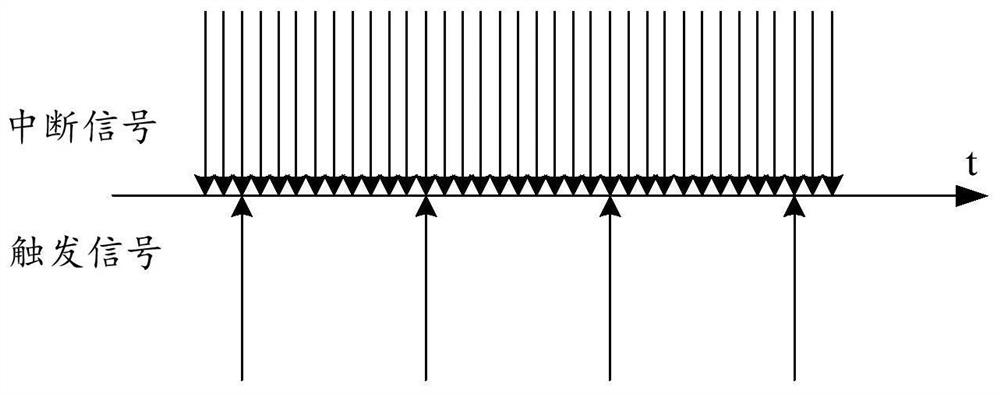

Image

  • Timestamp determination method and related equipment
  • Timestamp determination method and related equipment
  • Timestamp determination method and related equipment

Examples


Embodiment Construction

[0079] In order to make the object, technical solution and advantages of the present invention clearer, the implementation manner of the present invention will be further described in detail below in conjunction with the accompanying drawings.

[0080] Before explaining the embodiment of the present application in detail, the application scenarios involved in the embodiment of the present application are firstly introduced.

[0081] At present, in fields such as AR (augmented reality, augmented reality) and MR (mixed reality, mixed reality), it is usually necessary to accurately superimpose virtual targets in real space. In this case, it is necessary to estimate the position and attitude of the virtual target in real time. Information, that is, pose information.

[0082] For example, in an AR or MR game scene, virtual objects need to be placed in the real space, and the virtual objects need to maintain their original position and posture during the user's movement. The motion...


PUM


Abstract

The invention discloses a timestamp determination method and device and a computer storage medium, and belongs to the technical field of machine vision. In the application, if the data processing unit detects that the IMU caches the first IMU data at the first time point, the data processing unit sends a trigger signal for indicating exposure to the image acquisition unit. Therefore, the timestamp of the first image data and the timestamp of the first IMU data can be respectively determined by taking the first time point as the reference time point, and the timestamps of the first image data and the timestamp of the first IMU data are ensured to be determined in the same clock system. When the timestamp of the first image data is determined, the accurate timestamp of the first image data can be adaptively obtained only by compensating the first time point according to the exposure duration of the first image data no matter whether the image acquisition unit is in the automatic exposure mode or the fixed exposure mode. When the timestamp of the first IMU data is determined, the accurate timestamp can be obtained only by compensating the first time point according to the first time delay.

Description

technical field [0001] The present application relates to the technical field of machine vision, in particular to a time stamp determination method and related equipment. Background technique [0002] In VIO (visual inertial odometry, visual inertial measurement) technology, based on the angular velocity and acceleration data collected by IMU (inertial measurement unit, inertial measurement unit) and the image data collected by the image acquisition unit, the pose of the device can be accurately determined in real time information. Among them, the accuracy of the time stamp of the angular velocity and acceleration data, and the time stamp of the image data will affect the validity of the determined pose information to a certain extent. Therefore, how to determine the time stamp of these data is a problem that needs to be solved in VIO technology. [0003] For the convenience of subsequent description, the data collected by the IMU are collectively referred to as IMU data. ...

Claims


Application Information

Patent Timeline
Patent Type & Authority Applications(China)
IPC IPC(8): H04J3/06
CPCH04J3/0661
Inventor 彭真毛洋宋江新李杰毛慧浦世亮
Owner HANGZHOU HIKVISION DIGITAL TECH
Why Eureka
Eureka Blog
Learn More