Design method of vacuum chuck

A technology of vacuum suction cup and design method, which is applied in the directions of packaging, conveyor objects, transportation and packaging, etc. It can solve the problems of material loss and grasping effect, less sheet materials, etc., and achieve good suction effect

Active Publication Date: 2021-12-10
佛山松标智能装备有限公司
View PDF8 Cites 0 Cited by
  • Summary
  • Abstract
  • Description
  • Claims
  • Application Information

AI Technical Summary

Problems solved by technology

[0007] In order to overcome the defects and deficiencies in the above-mentioned prior art, the present invention provides a design method of a vacuum chuck. The purpose of the invention is to provide a new design method of a vacuum chuck. The vacuum chuck d

Method used


Image

  • Design method of vacuum chuck
  • Design method of vacuum chuck
  • Design method of vacuum chuck

Examples


Embodiment 1

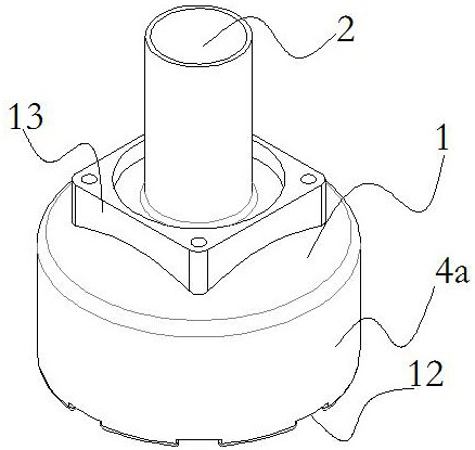
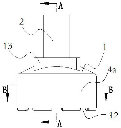
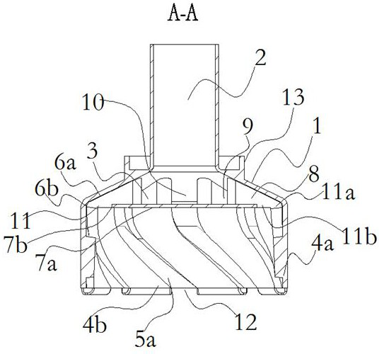
[0058] Refer to the attached figure 1 to attach Figure 7 , the present embodiment discloses a design method of a vacuum chuck, the designed vacuum chuck includes a chuck body 1, an air passage 2 and a vacuum chamber 3 communicating with each other are arranged in the suction cup body 1, and the vacuum chamber 3 is located below the air passage 2, The bottom of the suction cup body 1 is connected with a suction sleeve 4a, and the inner wall of the suction sleeve 4a is provided with a number of air suction grooves 5a;

[0059] The cavity shape of the vacuum chamber 3 is designed as an inverted funnel-shaped vacuum chamber 3, the opening end of the inverted funnel-shaped vacuum chamber 3 is connected with the suction sleeve 4a, and the closed end of the inverted funnel-shaped vacuum chamber 3 is connected with the air channel 2 The air channel 2, the vacuum chamber 3 and the suction sleeve 4a are coaxially arranged; the airtight partition 7a is arranged at the bottom of the vac...

Embodiment 2

[0065] As another preferred embodiment of the present invention, with reference to the attached figure 1 And attached figure 2As shown, this embodiment discloses a design method of a vacuum chuck. The designed vacuum chuck includes a chuck body 1, and an air passage 2 and a vacuum chamber 3 communicating with each other are arranged in the suction cup body 1. The vacuum chamber 3 is located in the air passage 2 Below, the suction sleeve 4a is connected to the bottom of the suction cup body 1, and a number of suction air grooves 5a are opened on the inner wall of the suction sleeve 4a;

[0066] The cavity shape of the vacuum chamber 3 is designed as an inverted funnel-shaped vacuum chamber 3, the opening end of the inverted funnel-shaped vacuum chamber 3 is connected with the suction sleeve 4a, and the closed end of the inverted funnel-shaped vacuum chamber 3 is connected with the air channel 2 The air channel 2, the vacuum chamber 3 and the suction sleeve 4a are coaxially ar...

Embodiment 3

[0085] In order to further highlight the difference between the effect of the vacuum suction cup designed by the design method of this application and the existing vacuum gripping device, the application made the following experiments:

[0086] Test conditions: (1) Vacuum pump fan is used as the negative pressure source, and the air extraction flow rate is 40m 3 / h;

[0087] (2) Picked and sorted objects: 90mm in diameter, 1.5mm in thickness, coarse grain cakes, sesame cakes or idyllic style cooking cakes, with a single cake weight of 10g;

[0088] (3) The vacuum suction cup is mounted on the delta three-axis manipulator.

[0089] Test sample one: use such as Figure 8 The structure of the vacuum chuck shown is that the vacuum chamber 3 is a cylindrical chamber, and a number of partition blocks 8 are arranged in the vacuum chamber 3, and vacuum air passages 9 are formed between the partition blocks 8, and the air suction groove 5a on the suction sleeve 4a adopts a parallel ...


PUM

PropertyMeasurementUnit
Diameteraaaaaaaaaa
Thicknessaaaaaaaaaa
Diameteraaaaaaaaaa

Abstract

The invention discloses a design method of a vacuum chuck, and belongs to the technical field of sorting and packaging machinery design. A vacuum cavity is arranged to be in an inverted funnel shape, and an air channel, an inverted funnel-shaped vacuum cavity and a suction sleeve are coaxially designed; a closed partition plate is arranged between the suction sleeve and the vacuum cavity, a suction air groove in the inner wall of the suction sleeve is designed into a spirally-distributed suction air groove, and an inner cavity of the suction sleeve is designed into a frustum-shaped inner cavity with a narrow upper part and a wide lower part; and the ratio of the sum of the cross sectional areas of all the suction air grooves in the inner wall of the suction sleeve to the cross sectional area of the air channel is controlled to range from 0.3 to 0.45. The vacuum chuck designed through the design method can grab 10-15 flaky materials at a time, the suction effect is good and stable, and the situation of material losing is not prone to occurring even if shaking occurs.

Description

technical field [0001] The invention relates to the technical field of sorting and packaging machinery design, and more specifically relates to a design method of a vacuum suction cup. Background technique [0002] Existing vacuum suction devices generally include a suction cup, a suction cup connector, a frame, and a vacuum generator assembly, and the vacuum generator assembly controls the suction cup connector to realize the action of the suction cup. This type of gripper can be used in applications requiring high-speed picking and sorting by robots or other handling equipment, and the products to be picked are items with standard outer contours such as pouches of medicine, biscuits and pouches of shampoo. [0003] This type of clamping technology mainly uses one or more vacuum suction cups, and each vacuum suction cup picks up one product at a time. Compared with the fact that each vacuum structure can pick up multiple items, this type of gripper has the problem of low g...

Claims


Application Information

Patent Timeline
IPC IPC(8): B65B35/38B65G47/91
CPCB65B35/38B65G47/91B65G2207/42B65G2201/0202
Inventor 黄松
Owner 佛山松标智能装备有限公司
Why Eureka
Try Eureka