

Electrostatic powder spraying room
A technology of electrostatic powder spraying and powder spraying room, which is applied in the direction of electrostatic spraying devices, spraying devices, liquid spraying equipment, etc., which can solve the problems of difficulty in powder suction and poor powder recovery effect, so as to improve the absorption effect, improve the recovery effect, Liquid effect
- Summary
- Abstract
- Description
- Claims
- Application Information
AI Technical Summary
Problems solved by technology
Method used
Image

Examples
Embodiment 1
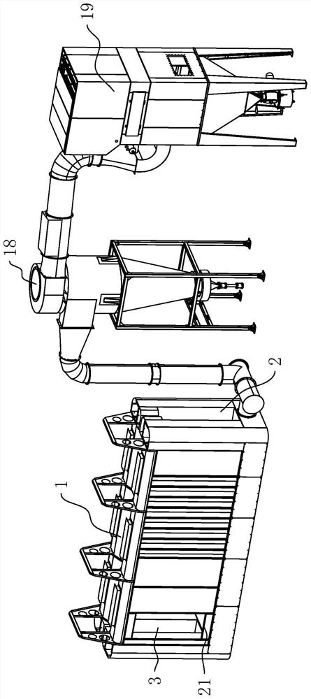
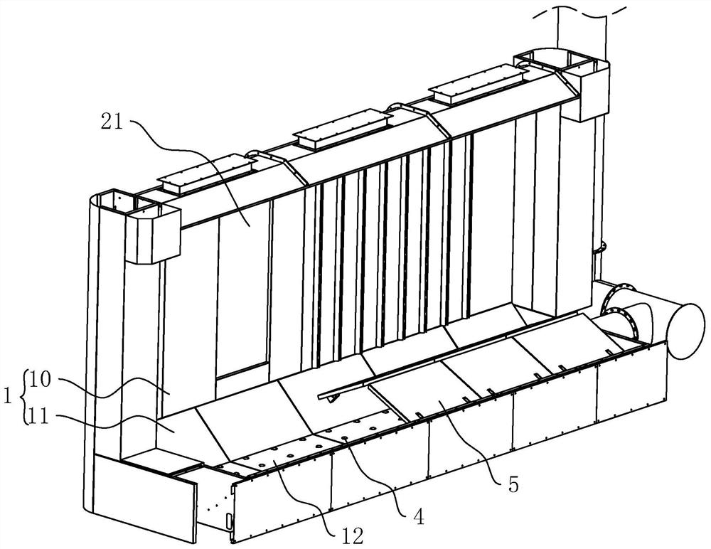
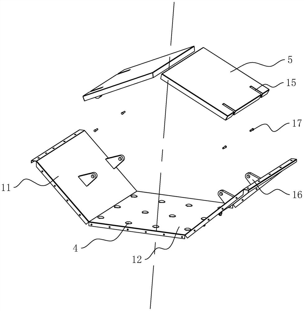
[0040] refer to figure 1 and figure 2 , the electrostatic powder spraying room includes a room body 1 with a hollow interior, the room body 1 includes a rectangular room panel 10 enclosing it, a side panel 11 bolted to the bottom of the room panel 10, and a bottom panel 12 fixedly connected to the bottom of the side panel 11, Two opposite side panels 11 are close to each other along the direction from top to bottom.
[0041] refer to figure 1 and figure 2 , One side of the room body 1 in the length direction is opened with a material inlet 2, and the other side is opened with a material outlet 3. During powder spraying, the workpiece is hung on the conveyor chain, and the workpiece is sent into the powder spraying room through the movement of the conveyor chain, and moves along the direction from the inlet 2 to the outlet 3. After the powder spraying is completed, the conveyor chain drives the workpiece to be discharged from the discharge port 3.
[0042] refer to figu...
Embodiment 2
[0057] refer to Figure 5 and Figure 6 , The difference between this embodiment and Embodiment 1 is that the powder guiding mechanism includes two horizontally arranged rotating rollers 80 that rotate through the powder spraying booth, and a conveyor belt 81 sleeved between the two rotating rollers 80 . The two rotating rollers 80 are located in the same horizontal plane, and the connecting line between the two rotating rollers 80 is parallel to the length direction of the room body 1 .
[0058] refer to Figure 5 and Figure 6 , the side wall of the conveyor belt 81 in the width direction is close to the inner wall of the room body 1 in the length direction, and the two inner walls of the room body 1 relative to the rotating roller 80 are fixedly connected with several baffles 83, and the baffles 83 are located in two adjacent spaces. Between the grooves 6 and closely attached to the belt.
[0059] refer to Figure 5 and Figure 6 , the blocking plate 83 cooperates wit...
PUM
 Abstract
Description
Claims
Application Information