Fixing device for workpiece edge-milling and specially-shaped workpiece edge-milling process

A technology for fixing devices and special-shaped workpieces, applied in positioning devices, clamping devices, metal processing machinery parts, etc., can solve the problems of inconvenient unloading and low processing efficiency, and achieve convenient operation, improved work efficiency, and simple operation Effect

Active Publication Date: 2018-08-03
MAANSHAN XINHUA HETEROTYPE STEEL DEV LIABILITY
View PDF7 Cites 1 Cited by
  • Summary
  • Abstract
  • Description
  • Claims
  • Application Information

AI Technical Summary

Problems solved by technology

[0006] Aiming at the inconvenient loading and unloading of traditional screw pressing and hydraulic pressing in the prior art, and low processing efficiency, the present invention provides a fixture for workpiece edge milling and a special-shaped workpiece edge milling process, with limited utilization The positioning block and the pressing device cooperate horizontally to compress or limit the workpiece laterally, which is convenient for milling and turning, with high processing efficiency, simple structure and convenient operation

Method used


Image

  • Fixing device for workpiece edge-milling and specially-shaped workpiece edge-milling process
  • Fixing device for workpiece edge-milling and specially-shaped workpiece edge-milling process
  • Fixing device for workpiece edge-milling and specially-shaped workpiece edge-milling process

Examples


Embodiment 1

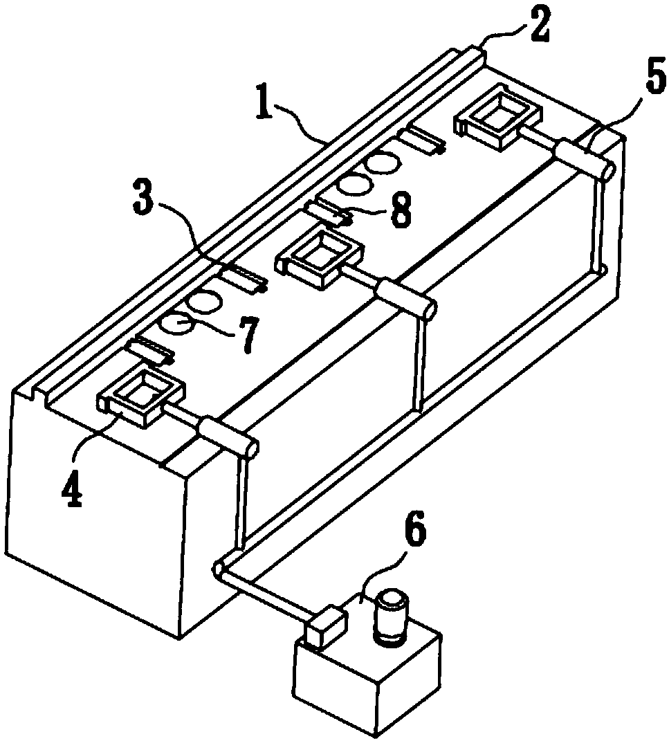
[0053] A fixture for workpiece edge milling, such as figure 1 As shown, it includes a fixed table 1 and a pressing device. The upper end surface of the fixed table 1 is horizontally fixed with a limit block 2. The bit blocks 2 are co-located front and back along the horizontal direction. The pressing device may be a pneumatic pressing device, a hydraulic pressing device, or a screw pressing device or the like. When the pressing device is a pneumatic pressing device or a hydraulic pressing device, the high pressure drives its movement output end to cooperate with the limiting block 2 to fix the workpiece. When the pressing device is a screw pressing device, the fixing of the workpiece can be realized by changing the screw-in length of the screw and cooperating with the limiting block 2 .

[0054] In a specific application, the workpiece to be processed is placed between the limit block 2 and the pressing device on the upper end surface of the fixed table 1, and the pressing d...

Embodiment 2

[0056] A fixture for workpiece edge milling in this embodiment has the same basic structure as that of Embodiment 1, the differences and improvements are as follows: figure 1 As shown, the compression device includes a compression block 4, a pressure transmission device 5 and a pressure supply device 6, and the pressure transmission device 5 is a pneumatic cylinder or a hydraulic cylinder, etc.; the pressure transmission device 5 is horizontally fixed on the fixed On the upper end surface of the table 1, the pressing block 4 is detachably connected to the output shaft of the pressure transmission device 5, and is set in cooperation with the limit block 2 in the horizontal direction. The pressing block 4 in this embodiment The connection mode between the block 4 and the pressure transmission device 5 is screw connection; the pressure supply device 6 is connected to the pressure transmission device 5 through a pipeline, and the pressure supply device 6 provides working pressure f...

Embodiment 3

[0061] A fixture for workpiece edge milling in this embodiment, the basic structure is the same as that of Embodiment 2, the differences and improvements are as follows: figure 1 As shown, the compression device includes a plurality of pressure transmission devices 5, and the output shaft of the pressure transmission device 5 can be detachably connected with the compression block 4. In this embodiment, the pressure transmission device 5 The connection between the output shaft and the pressing block 4 is screw connection; the pressure transmission devices 5 are evenly distributed along the length direction of the limiting block 2, and are all connected to the pressure supply device 6 through pipelines. A plurality of said pressing blocks 4 cooperate with said limiting blocks 2, and are fixed at multiple points along the length direction of the workpiece to be processed, and the distribution is uniform, the fixing effect is good, and the milling processing precision is high.


PUM


Abstract

The invention discloses a fixing device for workpiece edge-milling and a specially-shaped workpiece edge-milling process, and belongs to the technical field of edge-milling device processes. The fixing device comprises a fixing table and a pressing device, wherein a limiting block is fixedly arranged on the fixing table; the pressing device comprises a pressing block, a pressure transmission device and a pressure supply device; the pressure transmission device is horizontally fixed on the upper end surface of the fixing table; the pressing block is connected onto the output shaft of the pressure transmission device and is matched with the limiting block in the horizontal direction; the pressure supply device is connected with the pressure transmission device through a pipeline; and a supporting roller and a magnet are further arranged on the upper end surface of the fixing table. According to the fixing device disclosed by the invention, the pressing block, the limiting block and the magnet act with one another for fixing a workpiece onto the fixing table; the workpiece is transmitted to a rack or a next process through the supporting roller after edge-milling is completed, and anyposition on the material can be milled and processed. The fixing device is simple in structure, is convenient to operate, is high in processing efficiency, and is safe and reliable in processing process.

Description

technical field [0001] The invention belongs to the technical field of edge milling devices, in particular to a fixture for edge milling of workpieces and a process for edge milling of special-shaped workpieces. Background technique [0002] Edge milling is a process to remove excess or uneven parts of the edge of steel plates or special-shaped strips. It is usually completed by using an edge milling machine, but no matter what kind of edge milling machine is used, the processed material must be compressed and fixed. , so that it is in a fixed and stable state during processing. [0003] In the fixing device, it can be divided into screw pressing device and hydraulic pressing device. Among them, the use of the screw pressing device is time-consuming and labor-intensive, which affects the efficiency of edge milling. Hydraulic pressing solves the problem of production efficiency, but the design of edge milling hydraulic pressing device on the market currently adopts two colu...

Claims


Application Information

Patent Timeline
Patent Type & Authority Applications(China)
IPC IPC(8): B23Q3/08B23Q3/154B23C3/12
CPCB23C3/12B23Q3/062B23Q3/08B23Q3/154B23Q2703/04Y02P70/10
Inventor 杨师新高前龙赵道田汪礼才
Owner MAANSHAN XINHUA HETEROTYPE STEEL DEV LIABILITY
Why Eureka
Try Eureka