

Pipeline grinding device for building construction
A technology for building construction and pipelines, which is applied in the direction of grinding machines, manufacturing tools, grinding racks, etc., can solve the problems of unpolished, heavy operation of workers, and rusted pipelines, so as to improve the quality of grinding, improve the efficiency of grinding, and reduce manpower The effect of the operation
- Summary
- Abstract
- Description
- Claims
- Application Information
AI Technical Summary
Problems solved by technology
Method used
Image

Examples
specific Embodiment approach 1
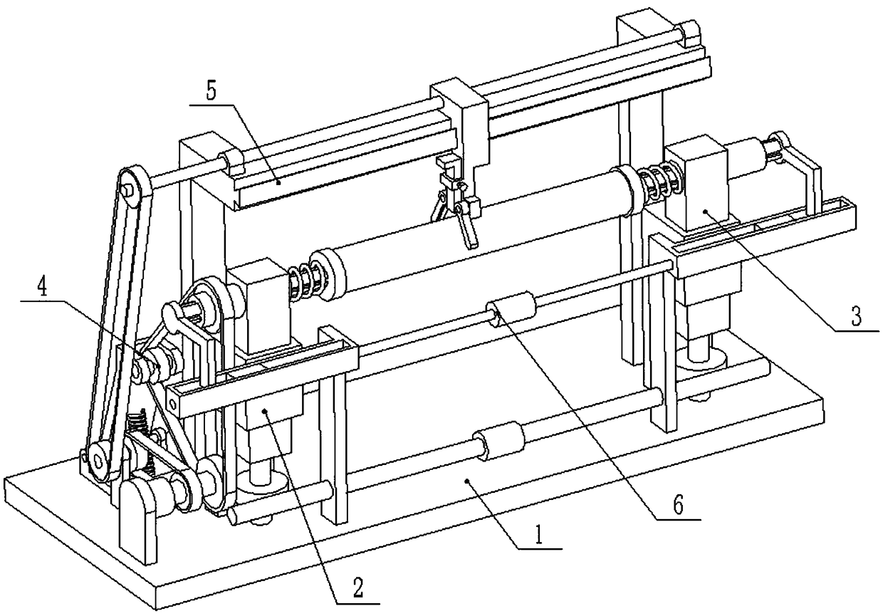
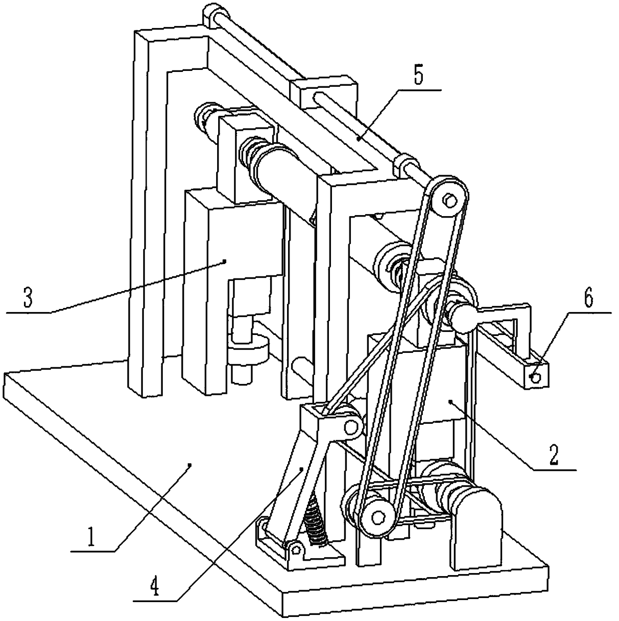
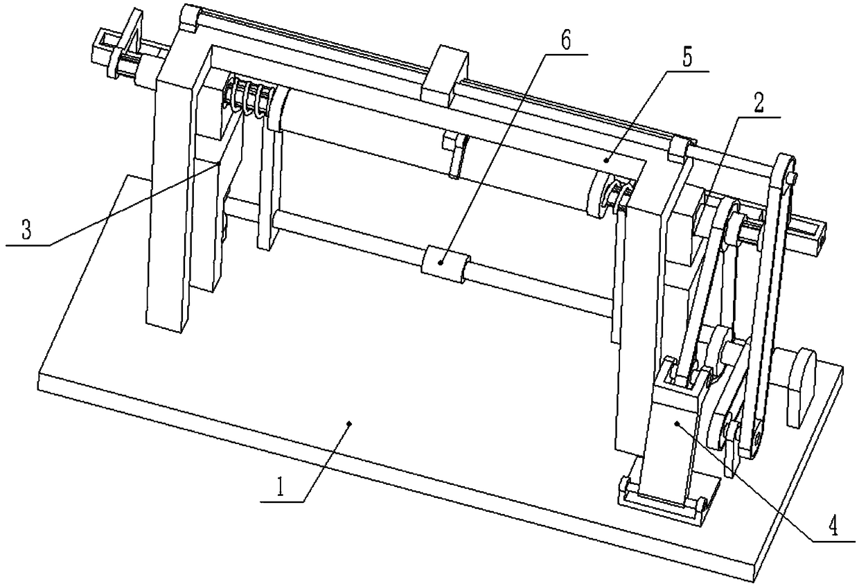
[0031] Combine below Figure 1-14Describe this embodiment, a pipe grinding device for building construction, including a base 1, a left support base 2, a right support base 3, a tensioning wheel 4, a support frame 5 and an adjustment rod 6, and the base 1 includes a bottom plate 1- 1. Motor 1-2, driving shaft 1-3, driving pulley I1-4, driving pulley II1-5, driven pulley I1-6, driven pulley II1-7, driven shaft 1-8 and The shaft frame plate 1-9; the motor 1-2 is fixedly connected to the base plate 1-1 through the motor frame, and one end of the drive shaft 1-3 is connected to the output shaft of the motor 1-2 through a coupling, and the drive shaft 1-3 The other end of the drive shaft is fixedly connected with the driving pulley I1-4, the middle end of the driving shaft 1-3 is fixedly connected with the driving pulley II1-5, the driving shaft 1-3, the driving pulley I1-4 and the driving pulley II1-5 Both rotate around their own axis and have axial positioning. The driving pulle...
specific Embodiment approach 2
[0035] Combine below Figure 1-14 To illustrate this embodiment, the tensioning pulley 4 includes a support seat 4-1, a rotating shaft 4-2, a shaft seat plate 4-3, a shaft fixing seat 4-4, a short shaft 4-5, and a tensioning pulley 4- 6 and tension spring 4-7; the support base 4-1 is fixedly connected on the driving pulley I1-4, and the two ends of the rotating shaft 4-2 are connected to the two ends of the support base 4-1 through bearings with seats respectively, and the rotating shaft 4-2 rotates around its own axis and has axial positioning. One end of the shaft seat plate 4-3 is fixedly connected to the rotating shaft 4-2, and the other end of the shaft seat plate 4-3 is fixedly connected to the shaft fixing seat 4-4. The shaft 4-5 is rotatably connected to the shaft holder 4-4 through the bearing with seat, the tension pulley 4-6 is fixedly connected to the short shaft 4-5, and the short shaft 4-5 and the tension pulley 4-6 are wound Its own axis rotates and has axial p...
specific Embodiment approach 3
[0036] Combine below Figure 1-14 To illustrate this embodiment, the left support base 2 also includes a left worm gear 2-5, the left worm gear 2-5 is fixedly connected to the left height adjustment screw 2-4, and the left worm gear 2-5 is located on the left height adjustment base 2-3 And between the bottom plate 1-1. The left worm wheel 2-5 rotates around its own axis and has axial positioning.
[0037]The right support base 3 also includes a right worm gear 3-5, the right worm gear 3-5 is fixedly connected to the right height adjustment screw rod 3-4, and the right worm gear 3-5 is located at the right height adjustment base 3-3 and the bottom plate 1-1 between. The right worm wheel 3-5 rotates around its own axis and has axial positioning.
[0038] The pipe polishing device for building construction also includes an adjustment rod 6, and the adjustment rod 6 includes a vertical frame plate 6-1, a worm screw 6-2, a screw ring I 6-3, a sliding seat 6-4, an adjustment Scr...
PUM
 Abstract
Description
Claims
Application Information