Efficient, energy-saving and low-emission fur dyeing machine and fur dyeing method

A high-efficiency, energy-saving, low-emission technology, applied in textile processing machine accessories, textiles and papermaking, liquid/gas/steam textile material treatment, etc., can solve problems such as difficulty in controlling bath ratio, affecting dyeing effect, uneven dyeing, etc., to achieve Reduce dyeing cost, improve dyeing effect and improve uniformity

Inactive Publication Date: 2014-07-16
TONGXIANG NEW ERA FUR
View PDF6 Cites 16 Cited by
  • Summary
  • Abstract
  • Description
  • Claims
  • Application Information

AI Technical Summary

Problems solved by technology

[0004] Now for fur dyeing, no matter using any of the above mechanisms, the fur is placed inside and turned inside through the turning mechanism, and because the amount of fur is relatively large in each dyeing process, resulting in contact with the cylindrical structure The pressure on the fur is relatively high, and the fur is easily damaged during the turning process, and it will cause uneven dyeing, and the dyeing time is relatively lo

Method used


Image

  • Efficient, energy-saving and low-emission fur dyeing machine and fur dyeing method
  • Efficient, energy-saving and low-emission fur dyeing machine and fur dyeing method
  • Efficient, energy-saving and low-emission fur dyeing machine and fur dyeing method

Examples


Embodiment 1

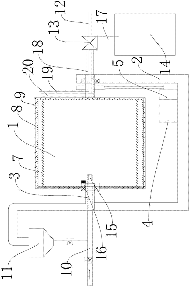
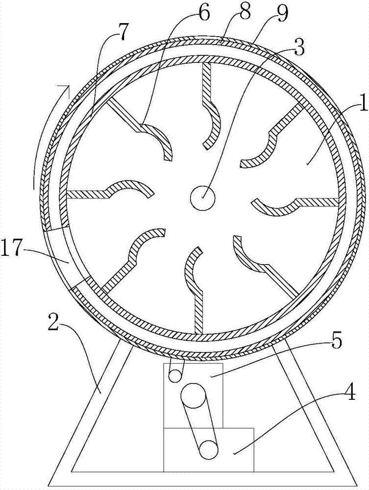
[0026] Such as figure 1 , figure 2 , Figure 4As shown, the high-efficiency, energy-saving and low-emission fur dyeing machine described in this embodiment includes a frame 2, a dyeing cylinder 1, a motor 4, a gearbox 5, and a control box; the dyeing cylinder 1 is respectively provided with shafts 3 on both sides, The shaft 3 is arranged on the frame 2, and one of the shafts 3 is connected to the dyeing cylinder 1 through a shaft 3 bearing, and is fixedly connected to the frame 2, and the other shaft 3 is fixed to the dyeing cylinder 1. Connected, connected with the frame 2 through the shaft 3 bearings, the motor 4 drives the dyeing cylinder 1 to rotate through the gearbox 5; a feed door is provided on the annular wall 7 of the dyeing cylinder 1, and the dyeing cylinder 1 The annular wall 7 is provided with a plurality of partitions 6, the partitions 6 extend from the annular wall 7 to the center of the dyeing cylinder 1, and the radial length of the partitions 6 is less th...

Embodiment 2

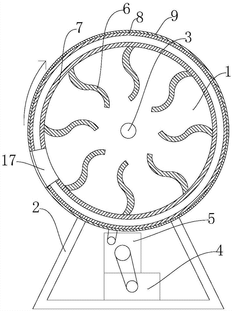
[0029] Such as figure 1 , image 3 , Figure 4 As shown, the high-efficiency, energy-saving and low-emission fur dyeing machine described in this embodiment includes a frame 2, a dyeing cylinder 1, a motor 4, a gearbox 5, and a control box; the dyeing cylinder 1 is respectively provided with shafts 3 on both sides, The shaft 3 is arranged on the frame 2, and one of the shafts 3 is connected to the dyeing cylinder 1 through a shaft 3 bearing, and is fixedly connected to the frame 2, and the other shaft 3 is fixed to the dyeing cylinder 1. Connected, connected with the frame 2 through the shaft 3 bearings, the motor 4 drives the dyeing cylinder 1 to rotate through the gearbox 5; a feed door is provided on the annular wall 7 of the dyeing cylinder 1, and the dyeing cylinder 1 The annular wall 7 is provided with a plurality of partitions 6, the partitions 6 extend from the annular wall 7 to the center of the dyeing cylinder 1, and the radial length of the partitions 6 is less th...


PUM


Abstract

The invention relates to the field of fur dyeing equipment, in particular to an efficient, energy-saving and low-emission fur dyeing machine. By the aid of the efficient, energy-saving and low-emission fur dyeing machine, a uniform and good dyeing effect can be realized. The efficient, energy-saving and low-emission fur dyeing machine comprises a framework, a dyeing drum, a motor and a gearbox. A plurality of partition plates are arranged on the inner annular wall of the dyeing drum, and a temperature detector is arranged in the dyeing drum. A bath ratio adopted in a fur dyeing method implemented by the aid of the efficient, energy-saving and low-emission fur dyeing machine is 1:2-5. The efficient, energy-saving and low-emission fur dyeing machine and the fur dyeing method have the advantages that the turning time of fur in the dyeing drum and the fur and dye contact time can be prolonged owing to the partition plates and structural arrangement of the partition plates, so that the dyeing uniformity can be effectively improved, wastage of dye can be reduced, the dye can be controlled precisely, the dyeing effect can be improved, and the dyeing cost can be greatly lowered.

Description

technical field [0001] The invention relates to the field of fur dyeing equipment, in particular to a high-efficiency, energy-saving and low-emission fur dyeing machine and a fur dyeing method. Background technique [0002] Existing fur dyeing mechanism: such as application number: 201010192474, named as a fur dyeing pot, discloses a fur dyeing pot, comprising a pot body, a pot mouth and a stirring device, and is characterized in that a heat insulating layer is provided on the pot body, A pot cover matched with the pot mouth is arranged on the pot mouth. The pot cover is provided with an insulating layer. The heat insulation layer and heat insulation layer are constructed with heat insulation materials in the middle of stainless steel materials on both sides. A return pipe is provided outside one side of the pot body, and the interfaces between the return pipe and one side of the pot body are respectively a liquid return inlet and a liquid return outlet, and a steam inlet ...

Claims


Application Information

Patent Timeline
IPC IPC(8): D06B3/10D06B23/00D06B23/20D06B23/22
Inventor 徐建龙
Owner TONGXIANG NEW ERA FUR
Why Eureka
Try Eureka