gear reducer

A technology of gear reduction and gear box, which is applied in the direction of gear lubrication/cooling, belt/chain/gear, mechanical equipment, etc., to achieve the effect of improving stability

Active Publication Date: 2022-02-25
常州市天磊传动机械有限公司 +1
View PDF0 Cites 0 Cited by
  • Summary
  • Abstract
  • Description
  • Claims
  • Application Information

AI Technical Summary

Problems solved by technology

[0004] The purpose of this invention is to provide a gear reducer to solve the technical problem of improving the stability of transmission shaft transmission

Method used


Image

  • gear reducer
  • gear reducer
  • gear reducer

Examples


Embodiment 1

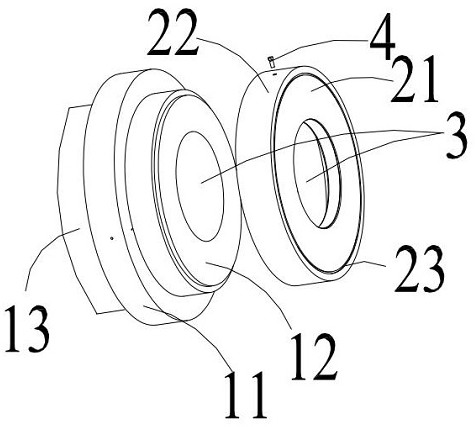
[0044] see Figure 1 to Figure 10 As shown, this embodiment provides a gear reducer, including: a gear box and a reduction gear assembly disposed in the gear box; wherein the reduction gear assembly includes a pair of transmission shafts 5 that pass through the side wall of the gear box at intervals and a plurality of gears 7 respectively sheathed on the transmission shaft 5 ; and a matching hole for rotating with the transmission shaft 5 is provided on the side wall of the gear box; and an oil baffle is sleeved on the transmission shaft 5 .

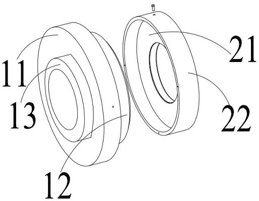
[0045] The oil baffle includes: a large eccentric wheel 1 and a small eccentric wheel 2 which are adapted to be locked and fixed by bolts 4 for example but not limited to; wherein the outer diameter of the large eccentric wheel 1 is greater than the outer diameter of the small eccentric wheel 2; and the large eccentric wheel 1 and the small eccentric 2 are provided with a through hole 3 that runs through but is not coaxial; the through h...

Embodiment 2

[0065] see Figure 1 to Figure 10 As shown, on the basis of the gear reducer in Embodiment 1, it is considered that the transmission shaft 5 and the through holes 3 of the large eccentric wheel 1 and the small eccentric wheel 2 are clearance fit, that is to say, there is a clearance, even if It is a very small gap, and lubricating oil may leak from the gap. Therefore, based on this problem, the gear reducer provided in this embodiment is also embedded with a sleeve in the through hole 3 of the small eccentric wheel 2. The washer 10 on the transmission shaft 5 is arranged coaxially with the through hole 3 . Through the cooperation of the washer 10 and the transmission shaft 5, the above-mentioned gap is blocked.

[0066] Here, between the circumferential side wall of the gasket 10 and the hole wall of the through hole 3 of the small eccentric wheel 2, for example but not limited to, sealing colloid can be used to achieve an effective sealing fit, so as to prevent the lubricati...

Embodiment 3

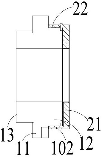
[0068] see Figure 1 to Figure 10 As shown, on the basis of the gear reducer of Embodiment 2, the washer 10 used in the gear reducer of this embodiment has a hollow storage chamber 101, and the hollow storage chamber 101 is wound around the outer circumference of the transmission shaft 5 and at least one oil inlet is provided on the contact surface between the washer 10 and the hole wall of the through hole 3 of the small eccentric wheel 2, and the large eccentric wheel 1 and the small eccentric wheel 2 are respectively provided with a The oil passage 102 communicated with the oil port. Here, the oil inlets correspond to the oil passages one by one, that is, the number of oil inlets corresponds to the number of oil passages, which is not absolutely limited in this embodiment.

[0069] To be more specific, the oil passage 102 provided on the large eccentric 1 includes the oil inlet hole provided on the circumferential side wall of the base 11 of the large eccentric 1, and the ...


PUM


Abstract

The invention discloses a gear reducer, which comprises a gear box and a reduction gear assembly arranged in the gear box; wherein the reduction gear assembly includes a pair of transmission shafts passing through the side wall of the gear box at intervals and sleeved on the transmission shaft respectively. There are several gears on the shaft; and on the side wall of the gear case, there is a matching hole that is rotatably matched with the transmission shaft; and an oil baffle is set on the transmission shaft; the oil baffle includes a large The eccentric wheel and the small eccentric wheel; the outer diameter of the large eccentric wheel is larger than the outer diameter of the small eccentric wheel; and the large eccentric wheel and the small eccentric wheel are provided with through holes that pass through but are not coaxial; and are respectively arranged on the large eccentric wheel and the small eccentric wheel The apertures of the through holes of the wheels are the same. The invention can effectively improve the transmission stability of the transmission shaft.

Description

technical field [0001] The invention relates to the technical field of gears, in particular to a gear reducer. Background technique [0002] Gear reducers are generally used in transmission equipment with low speed and high torque, and convert the small torque output by the motor into large torque through the gear reducer. Generally speaking, a gear reducer includes a gear box and a gear shaft located in the gear box; the gear box includes an upper gear case and a lower gear case that are connected together. For the overall gear shaft, its operation The stability in the process depends on the stability of the joint between the upper gear case and the lower gear case. Here, if there is looseness in the joint between the upper gear case and the lower gear case, it will directly affect the gear shaft. transmission stability. [0003] In addition, the side wall of the gear box is provided with a shaft hole for fitting the gear shaft. In order to prevent the lubricating oil in ...

Claims


Application Information

Patent Timeline
Patent Type & Authority Patents(China)
IPC IPC(8): F16H57/04F16H57/021
CPCF16H57/0427F16H57/043F16H57/045F16H57/021
Inventor 王建南李建全李建忠王璐颖
Owner 常州市天磊传动机械有限公司
Why Eureka
Try Eureka