Heat energy recycling system utilizing rubber wood carbon

A heat energy recovery and waste heat recovery technology, which is applied in the steam generation method using heat carrier, indirect heat exchanger, heat exchanger type, etc., can solve the problems of affecting the surrounding environment, environmental pollution, waste of resources, etc.

Pending Publication Date: 2021-12-10
勐腊海发木材有限责任公司
View PDF0 Cites 0 Cited by
  • Summary
  • Abstract
  • Description
  • Claims
  • Application Information

AI Technical Summary

Problems solved by technology

[0002] At present, in the process of carbon production on the market, a large amount of waste heat gas containing harmful gases will be generated, and the heat in it will not be recycled, resulting in a great waste of resources, and because the carbon

Method used


Image

  • Heat energy recycling system utilizing rubber wood carbon
  • Heat energy recycling system utilizing rubber wood carbon
  • Heat energy recycling system utilizing rubber wood carbon

Examples


Embodiment 1

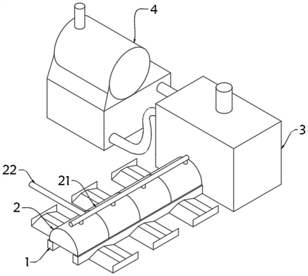
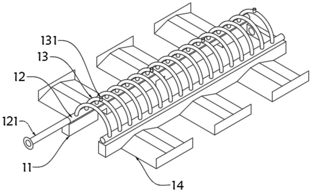
[0027] The invention provides a heat recovery and utilization system utilizing rubber wood carbon, such as Figure 1-Figure 2 As shown, it includes a waste heat recovery mechanism 1, which is used to process and recover the waste heat generated in the carbon production process. One end of the waste heat recovery mechanism 1 is connected to a combustion furnace 3, which is used to fully burn the waste heat and remove harmful gases such as carbon monoxide inside. One end of the combustion furnace 3 is connected with a fluidized fluidized furnace 4 for further recycling the waste heat generated in the combustion furnace 3. A sealing cover 2 is installed on the top of the waste heat recovery mechanism 1 to seal the top of the waste heat recovery mechanism 1 to avoid To dissipate the heat, a steam recovery pipeline 21 is installed on the top of the sealing cover plate 2 for recovering the steam generated by the waste heat recovery mechanism 1 for convenient transmission and utilizat...

Embodiment 2

[0033] In order to further improve the utilization efficiency of waste heat in the combustion furnace 3, as Figure 3-4 As shown, an outer wall of one side of the combustion furnace 3 is provided with an air inlet 31, and an igniter 32 is installed near the air inlet 31 on the inner wall of the combustion furnace 3, for igniting the waste heat that is passed in to make it fully combustible, and the combustion furnace 3 The upper part of one side of the outer wall is provided with a hot gas outlet 33, and the lower part of one side of the outer wall of the combustion furnace 3 is provided with a circulation inlet 34, which recycles the gas passed into the fluidized fluidized furnace 4 after use, so that the remaining heat can be continuously used to avoid energy loss.

[0034] Further, a waste heat circulation pipe 41 is installed inside the fluidized fluidized furnace 4 , a waste heat inlet pipe 42 is arranged on the upper part of the outer wall of the fluidized fluidized furna...


PUM


Abstract

The invention discloses a heat energy recycling system utilizing rubber wood carbon. The system comprises a waste heat recycling mechanism, one end of the waste heat recycling mechanism is connected with a combustion furnace, one end of the combustion furnace is connected with a fluidized bed furnace, the top of the waste heat recycling mechanism is provided with a sealing cover plate, and the top of the sealing cover plate is provided with a steam recycling pipeline. And one end of the steam recycling pipeline is connected with a primary waste heat discharge pipe. According to the heat energy recycling system utilizing the rubber wood carbon, the waste heat recycling mechanism can recycle the waste heat generated in the carbon production process, steam is generated after water is heated by the waste heat, then the steam is conveyed into a wood drying process to dry wood, and the waste heat can be subjected to secondary combustion through the combustion furnace. The harmful gases such as carbon monoxide inside can be removed after sufficient combustion, generated heat further enters the fluidized bed furnace to be recycled, the fluidized bed furnace can further utilize the waste heat generated by the combustion furnace, the water is heated to generate water vapor, and the water vapor is conveyed into the wood drying process to further dry the wood.

Description

technical field [0001] The invention relates to the technical field of waste heat recovery equipment, in particular to a heat recovery and utilization system utilizing rubber wood carbon. Background technique [0002] At present, in the process of carbon production on the market, a large amount of waste heat gas containing harmful gases will be generated, and the heat in it will not be recycled, resulting in a great waste of resources, and because the carbon production process is basically incomplete combustion , so some harmful gases will be produced, and the emission of carbon monoxide and other gases to the outside will easily cause environmental pollution and affect the surrounding environment. Contents of the invention [0003] The object of the present invention is to provide a thermal energy recovery and utilization system using rubber wood carbon to solve the problems raised in the above-mentioned background technology. [0004] In order to achieve the above objec...

Claims


Application Information

Patent Timeline
IPC IPC(8): F28D7/08F22B1/18F26B21/00F23G7/06
CPCF28D7/082F22B1/18F26B21/005F23G7/06
Inventor 苏兆华苏子勇
Owner 勐腊海发木材有限责任公司
Why Eureka
Try Eureka