Device and method for detecting compaction degree of on-site filling roadbed based on shear wave velocity

A detection device and shear wave technology, which is applied in the direction of using sound wave/ultrasonic wave/infrasonic wave to analyze solids, analyze materials, instruments, etc. It can solve the problems of large disturbance, insufficient reliability, and difficulty in taking out complete core samples, so as to ensure accuracy performance and reliability, and the effect of reducing crowding disturbances

Active Publication Date: 2021-12-10
SHANDONG UNIV +1
View PDF9 Cites 2 Cited by
  • Summary
  • Abstract
  • Description
  • Claims
  • Application Information

AI Technical Summary

Problems solved by technology

However, the inventors have found that the volume of the probe rod itself will have an obvious impact on the soil, causing the nearby soil to be compacted
Not only increases the difficulty of the bending element test piece extending into the soil, but also significantly affects the reliability of the wave velocity test results
At the same time, simple subgrade soil coring faces difficulties such as difficulty in taking out complete core samples, and large disturbances after taking out, and it is not reliable enough to detect the compaction effect of filling soil simply by coring

Method used


Image

  • Device and method for detecting compaction degree of on-site filling roadbed based on shear wave velocity
  • Device and method for detecting compaction degree of on-site filling roadbed based on shear wave velocity
  • Device and method for detecting compaction degree of on-site filling roadbed based on shear wave velocity

Examples


Embodiment 1

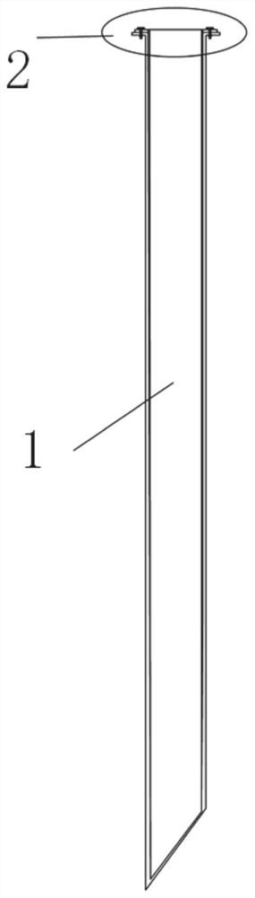
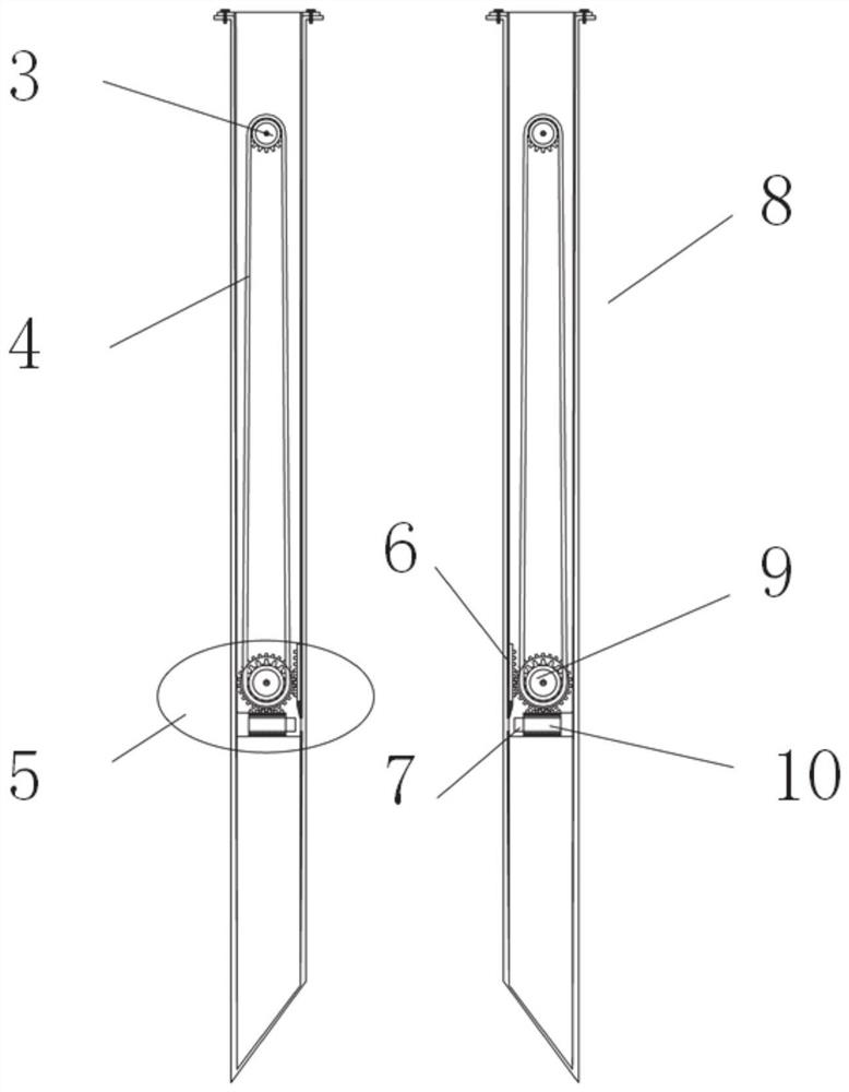
[0056] In a typical embodiment of the present invention, refer to figure 2 As shown, the on-site filling subgrade compaction detection device based on shear wave velocity includes a shear wave excitation mechanism and a shear wave receiving mechanism 8, which can be inserted into the filling subgrade at a set distance, and the shear wave excitation mechanism and the shear wave receiving mechanism both include an outer casing 101 , an inner core tube 103 for taking soil, and an inner core rod 11 of a bending element.

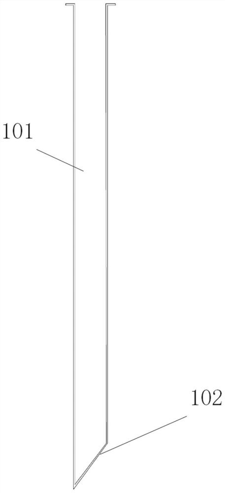
[0057] an outer casing with a hollow interior, and a first opening is provided on the side wall;

[0058] Soil-taking core pipe, both inside and bottom are hollow, refer to Figure 4 shown, and can be detachably connected with the outer casing, so that when the outer casing is inserted into the soil, the soil inside the outer casing enters the soil-absorbing inner core pipe, and the soil-absorbing inner core pipe can be moved relative to the outer casing under ...

Embodiment 2

[0091] The difference between this embodiment and Embodiment 1 is:

[0092] The moving mechanism is a first linear drive mechanism, the first linear drive mechanism is fixed in the rod body, and the first linear drive mechanism is connected with the bending element test piece to drive the bending element test piece to move;

[0093] A movable opening and closing door is arranged in the rod body at the second opening, and the opening and closing door is connected with the second linear drive mechanism to drive the opening and closing door to close or open the second opening.

[0094] Specifically, both the first linear drive mechanism and the second linear drive mechanism can be drive motors, the first motor drives the linear movement of the bending element test piece, and the first motor drives the bending element test piece to reciprocate through the rack and pinion mechanism. linear motion;

[0095] The second motor is fixed above the second opening of the rod body, the sec...


PUM


Abstract

The invention discloses a device and a method for detecting the compaction degree of an on-site filling roadbed based on shear wave velocity, and solves the problems that in the prior art, a feeler lever can generate an embedding and extruding effect on a soil body and a bending element is in close contact with roadbed soil to be detected. The device and the method can improve the reliability of a shear wave test result. According to the specific scheme, the device for detecting the compaction degree of an on-site filling roadbed based on shear wave velocity comprises a shear wave excitation mechanism and a shear wave receiving mechanism, and each of the shear wave excitation mechanism and the shear wave receiving mechanism comprises an outer sleeve, a soil sampling inner core pipe and a bending element inner core rod; a first opening is formed in the side wall of the outer sleeve; the soil sampling inner core pipe can be detachably connected with the outer sleeve, so that when the outer sleeve is cut into a soil body, the soil body in the outer sleeve enters the soil sampling inner core pipe, and the soil sampling inner core pipe can move relative to the outer sleeve under the action of external force; and the bending element inner core rod comprises a hollow rod body which can be connected with the outer sleeve, the rod body is provided with a second opening which can be communicated with the first opening, and a movable bending element test piece is arranged in the rod body.

Description

technical field [0001] The invention relates to the field of geotechnical engineering, in particular to a device and a method for detecting the compaction degree of an on-site filled soil subgrade based on shear wave velocity. Background technique [0002] The statements in this section merely provide background information related to the present invention and do not necessarily constitute prior art. [0003] The subgrade is an important part of the highway line, but the current subgrade filling project is facing problems such as tight construction schedule and complicated compaction effect detection. With the gradual popularization of large-tonnage rollers and large-thickness paving technology, traditional compaction detection methods, such as sand filling method, are no longer applicable, and it is difficult to meet the needs of compaction detection under large-thickness paving conditions. [0004] Existing studies have shown that the compaction state of the soil can be r...

Claims


Application Information

Patent Timeline
Patent Type & Authority Applications(China)
IPC IPC(8): G01N29/07
CPCG01N29/07G01N2291/023
Inventor 蒋红光李宜欣马川义周鹏飞王凯王育杰姚占勇张吉哲姚凯梁明
Owner SHANDONG UNIV
Why Eureka
Try Eureka