
Serial port network switch based on logic switch

A technology of network switches and logical switches, applied in the field of serial network switches based on logical switches, and serial network switches, can solve problems such as network disconnection, damaged network switch interfaces, and poor network contact, so as to ensure stability, avoid poor contact, The effect of convenient rotation mechanism

Inactive Publication Date: 2021-12-10
马良华
View PDF0 Cites 0 Cited by
  • Summary
  • Abstract
  • Description
  • Claims
  • Application Information

AI Technical Summary

Problems solved by technology

[0003] Most of the positions where the existing network switches are placed are exposed to the external environment, and most of the external environments contain some dust. Since the ports of the network switches do not have the dustproof function, the network switches are exposed to the external environment for a long time. In the environment, a small amount of dust will enter the port and cover the copper wire inside the network card interface. When the crystal head is inserted into the inside of the network card interface, it is easy to cause poor network contact or network disconnection. At the same time, the network switch network card interface and The crystal head is connected by plugging. Since the connection is not properly fixed and protected, it is easy to cause poor network contact or disconnection of the network when someone knocks over the network cable, and even damage the interface of the network switch.

Method used


Image

  • Serial port network switch based on logic switch
  • Serial port network switch based on logic switch
  • Serial port network switch based on logic switch

Examples


Embodiment Construction

[0037] The following will clearly and completely describe the technical solutions in the embodiments of the present invention with reference to the accompanying drawings in the embodiments of the present invention. Obviously, the described embodiments are only some, not all, embodiments of the present invention. Based on the embodiments of the present invention, all other embodiments obtained by persons of ordinary skill in the art without making creative efforts belong to the protection scope of the present invention.

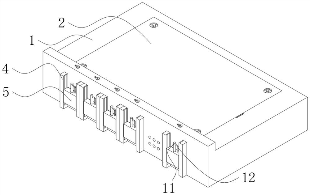
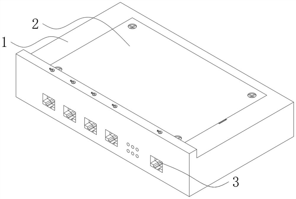
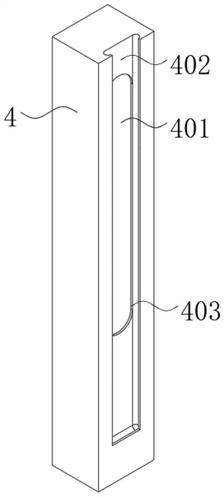
[0038] see Figure 1-9 As shown, a serial port network switch based on a logical switch, including:

[0039]The switch body 1. The front of the switch body 1 is provided with a plurality of network card interfaces 3 equidistantly. The network card interfaces 3 can be processed into corresponding shapes according to the needs. The network card interface 3 is used to connect the crystal head of the external wiring. There is a top plate 2, which can prevent exte...


PUM


Abstract

The invention discloses a serial port network switch based on a logic switch, and the switch comprises a switch body, an external connection plate, a shielding mechanism, a clamping mechanism and a rotating mechanism; a plurality of network card interfaces are formed in the front face of the switch body at equal intervals, a top plate is assembled above the switch body, and the external connection plate is fixedly connected to the front face of the switch body; the shielding mechanism is arranged at the joint of the network card interface and the external connection plate, the positioning mechanism is arranged at the joint of the protection block and the switch body, the clamping mechanism is arranged in the switch body, and the rotating mechanism is arranged at the bottom end of the protection block. The beneficial effects of the invention are that the design of the shielding mechanism is utilized, and the shielding mechanism can play a role in shielding and protecting the network card interface, so that electrical components in the network card interface of the switch body are not exposed in an external environment, dust in the external environment is prevented from entering the network card interface, and a copper wire in the network card interface is covered.

Description

technical field [0001] The invention relates to a serial network switch, in particular to a logical switch based serial network switch, which belongs to the technical field of logical switches. Background technique [0002] With the development and rise of the Internet of Things, industrial remote monitoring, and smart homes, it has become a trend that more and more smart instruments need to be connected to the network, and network switches also appear. Provide more connection ports in the subnet to connect more computers. A logical switch is a type of network switch. A logical switch uses network aggregation to centralize and simplify virtual network provisioning, management, and monitoring. Specifically, administrators can Interacts with logical switches to define what functions should be held in a virtual network, while logical switches can be connected to third-party connectors. [0003] Most of the positions where the existing network switches are placed are exposed to...

Claims


Application Information

Patent Timeline
IPC IPC(8): H04Q1/02
CPCH04Q1/028H04Q1/06H04L49/10
Inventor 马良华
Owner 马良华
Learn More