Stirring drum internally provided with grooves and stirring mill

A mixing drum and mill technology, applied in grain processing, etc., can solve the problems of inconvenient use, large lining area, and high labor intensity of the stirring mill, and achieve the goal of reducing the probability of direct collision with the inner wall of the mixing drum and reducing the wear rate Effect

Pending Publication Date: 2021-12-14
CHENGDU LEEJUN IND
View PDF0 Cites 0 Cited by
  • Summary
  • Abstract
  • Description
  • Claims
  • Application Information

AI Technical Summary

Problems solved by technology

Due to the large volume of the mixing drum, the area of ​​the inner lining to protect the mixing drum is also correspondingly larger. When the inner lining needs to be replaced, the labor intensity of removing the old inner lining and replacing it with a new inner lining will be very high. Therefore, a single Relying on the lining to protect the mixing drum will also cause inconvenience to the use of the stirring mill

Method used


Image

  • Stirring drum internally provided with grooves and stirring mill
  • Stirring drum internally provided with grooves and stirring mill
  • Stirring drum internally provided with grooves and stirring mill

Examples


Embodiment 1

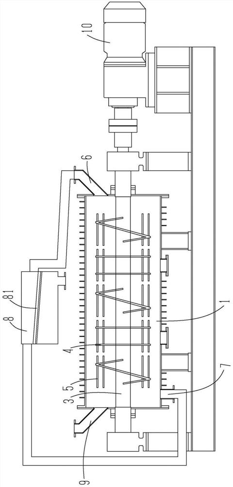
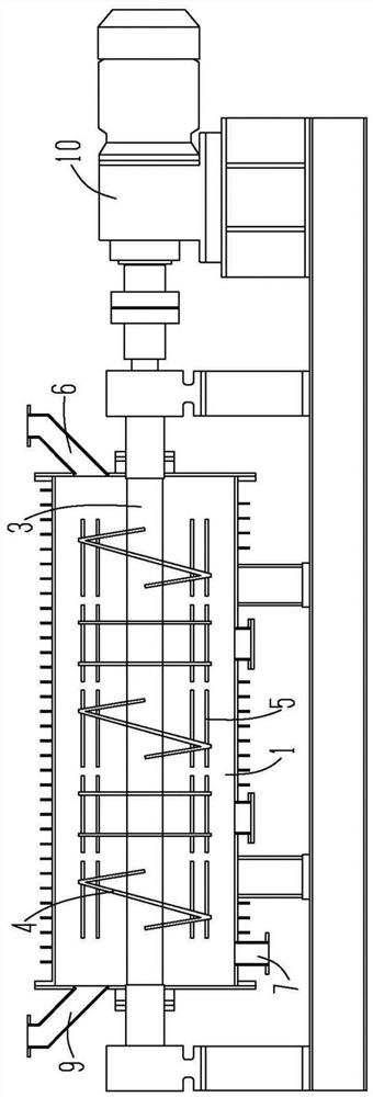
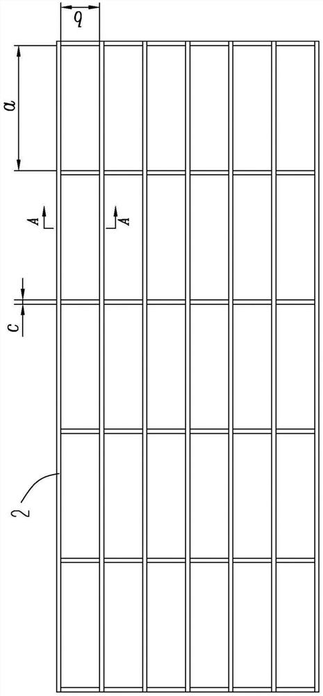
[0035] Please see Figure 1 to Figure 4 , a mixing drum 1 with grooves inside, the main body is the mixing drum 1, which is filled with grinding media, the inner wall of the mixing drum 1 is arranged with a number of lining plates 2 at intervals, and the gap between the lining plates 2 and the lining plates 2 is formed The grooves are arranged along the radial and axial directions of the mixing drum 1, and all the grooves are combined to form a grid shape. When the grinding medium is doing centrifugal movement, it is moved to the inner wall of the mixing drum 1 by the action of centrifugal force. Since the grinding medium moves at a high speed during the grinding process, it is easy to be stuck in the groove; after the maximum number of all grinding media is stuck in the groove, A protective layer will be formed, and most of the other grinding media that do centrifugal movement will collide with the grinding media stuck in the groove and fixed on the inner wall of the mixing d...

Embodiment 2

[0045] Please see Figure 5 , different from the way of forming the grooves in Example 1: the inner wall of the mixing drum 1 is provided with a liner 2, the grooves are set on the liner 2, the grooves are arranged along the radial and axial directions of the mixing drum 1, all the grooves Combine to form a grid shape. The grinding medium is completely isolated from the mixing drum 1. Before the grinding medium is stuck into the groove, the lining plate 2 collides first; the lining plate 2 itself has a groove, and the grinding medium is stuck in the groove on the lining plate 2 to assist The liner 2 protects the mixing drum 1 and prevents the wear of the mixing drum 1; the grinding medium stuck in the groove also protects the liner 2 to a certain extent and reduces the wear rate of the liner 2.

Embodiment 3

[0047] Different from the way of forming the grooves in Embodiment 1 and Embodiment 2: the inner wall of the mixing drum 1 is directly provided with grid-shaped grooves, without fixing the liner 2, and the mixing drum 1 is directly made into the required shape in the early stage.


PUM


Abstract

The invention discloses a stirring drum internally provided with grooves and a stirring mill, and relates to the technical field of stirring and grinding equipment. A grinding medium is contained in the stirring drum, the plurality of grooves are formed in the inner wall of the stirring drum, and the minimum width and the minimum length of the grooves are larger than the maximum width of the grinding medium. The stirring mill comprises the stirring drum. When the grinding medium does high-speed centrifugal motion in the stirring drum, the grinding medium is easy to hit to the inner wall of the stirring drum at a high speed and hit into the grooves due to the limited volume of the stirring drum; and due to the width setting of the grooves, the grinding medium is supported by the side walls of the grooves and is fixed in the grooves when the grinding medium is hit into the grooves. When the maximum number of grinding media are clamped in all the grooves, a protective layer is formed on the inner wall of the stirring drum, and other subsequent grinding media collide with the grinding media clamped in the grooves, so that the probability that the grinding media directly collide with the inner wall of the stirring drum is reduced, and the abrasion rate of the inner wall of the stirring drum is reduced.

Description

technical field [0001] The invention relates to the technical field of stirring and grinding equipment, in particular to a stirring drum and a stirring mill with internal grooves. Background technique [0002] Stirring mill is equipment for grinding materials. The grinding method is to use the agitator inside the mixing drum to drive the material and grinding medium to move. The grinding medium collides and squeezes the material during the movement, and grinds the coarse material into fine material. During the grinding process, the agitator stirs the material inside the mixing drum and the grinding medium, making them centrifugally move inside the mixing drum. During the high-speed rotation of the agitator, the grinding medium moves towards the inner wall of the mixing drum, causing the grinding medium to collide with the inner wall of the mixing drum. If things go on like this, the inner wall of the mixing drum will be worn and affect the grinding effect. In severe cases, t...

Claims


Application Information

Patent Timeline
Patent Type & Authority Applications(China)
IPC IPC(8): B02C17/22B02C17/16B02C17/10
CPCB02C17/22B02C17/16B02C17/10
Inventor 何亚民丁亚卓徐智平
Owner CHENGDU LEEJUN IND
Why Eureka
Try Eureka