Supercharge Your Innovation With Domain-Expert AI Agents!

Synchronous material supporting structure of sheet metal forming automatic production line

An automatic production line and sheet metal technology, applied in the direction of conveyors, packaging, mechanical conveyors, etc., can solve the problems of small adjustment range and cumbersome control, etc., and achieve the effect of simple control and easy operation

Pending Publication Date: 2021-12-14
青岛海一诺德工业自动化有限公司
View PDF1 Cites 0 Cited by
  • Summary
  • Abstract
  • Description
  • Claims
  • Application Information

AI Technical Summary

Problems solved by technology

[0004] In the above technical solution, the existing adjustable-width support structure has the problems of small adjustment range and cumbersome control

Method used


Image

  • Synchronous material supporting structure of sheet metal forming automatic production line
  • Synchronous material supporting structure of sheet metal forming automatic production line
  • Synchronous material supporting structure of sheet metal forming automatic production line

Examples


Embodiment 1

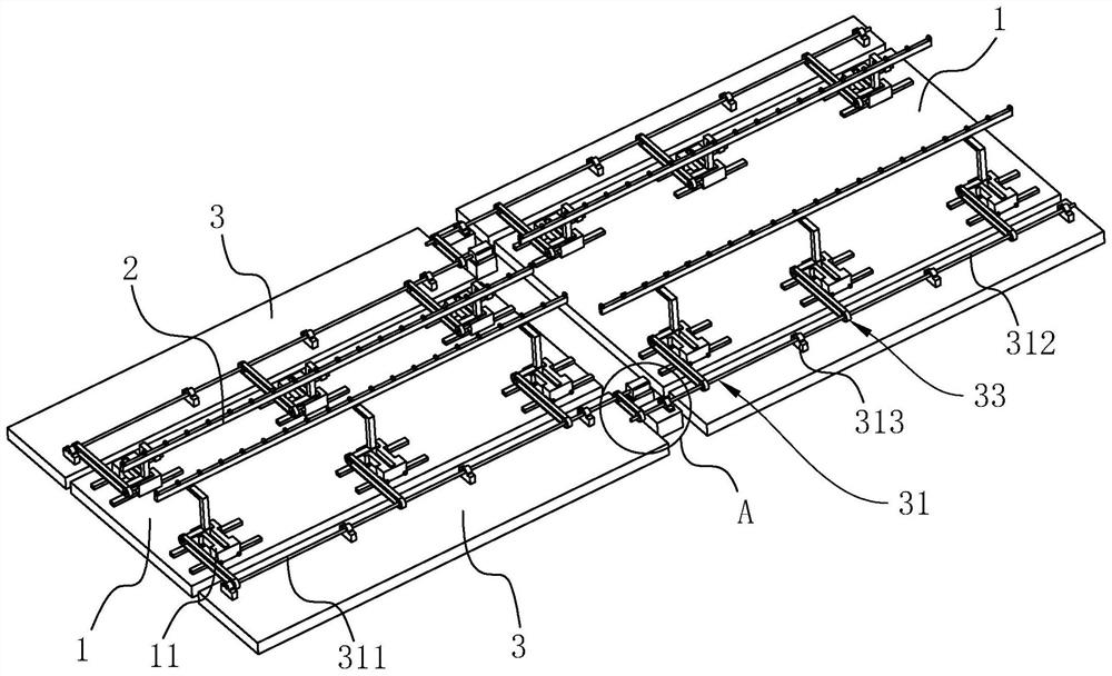
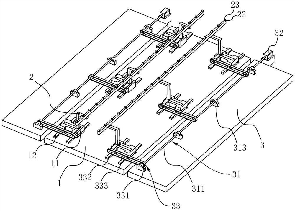
[0039] Embodiment 1. The present invention provides a synchronous support structure for an automatic sheet metal forming production line, such as figure 1 and figure 2 As shown, it includes a main frame body 1 and a plurality of sliding brackets 2 slidingly connected to the main frame body 1. The sliding brackets 2 slide along a direction perpendicular to the length of the sliding brackets 2. The length directions of all sliding brackets 2 are mutually Parallel, the sliding brackets 2 are divided into two groups and the two groups of sliding brackets 2 are all connected end to end along their own length direction.

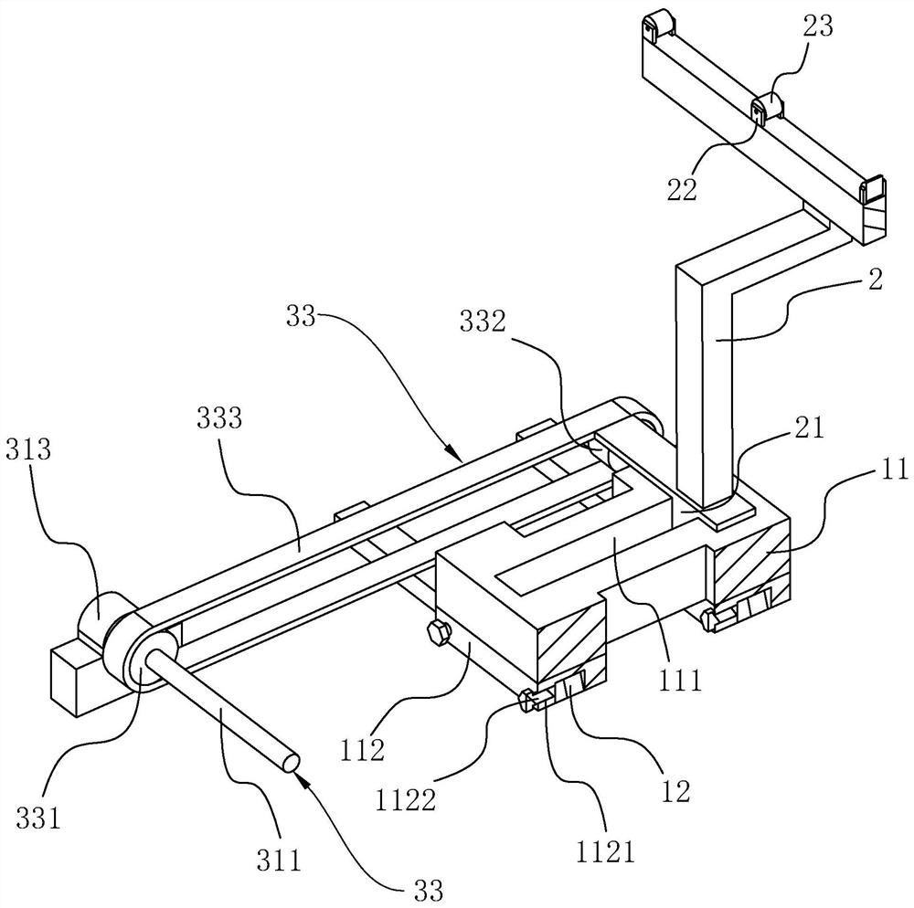
[0040] Such as figure 2 and image 3 As shown, the top of the sliding bracket 2 is fixedly connected with a plurality of roller seats 22, and each roller seat 22 is rotatably connected with a supporting roller 23, and the supporting rollers 23 are arranged along a direction perpendicular to the length of the sliding bracket 2. . The support roller 23 changes ...

Embodiment 2

[0047] Embodiment 2. The present invention provides a synchronous support structure for an automatic sheet metal forming production line, such as Figure 5 As shown, the difference from Embodiment 1 is that the synchronization assembly 33 includes a first gear 334 fixedly connected to the rotating shaft 31, the sliding bracket 2 is rotatably connected with a second gear 335, the first gear 334 and the second gear 335 A synchronous rack 336 is sleeved together, and the sliding bracket 2 is fixedly connected to the synchronous rack 336 . Rotation of the rotating shaft 31 drives the first gear 334 to rotate, the first gear 334 drives the second gear 335 to rotate through the synchronous rack 336, and the rotation of the synchronous rack 336 can drive the sliding bracket 2 to move.

[0048] The main frame body 1 is fixedly connected with a slide rail 13 perpendicular to the length direction of the slide bracket 2 at the position corresponding to each slide bracket 2, and each slid...


PUM


Abstract

The invention relates to the technical field of sheet metal production line transportation, in particular to a synchronous material supporting structure of a sheet metal forming automatic production line. The structure comprises a main frame body and a plurality of sliding brackets connected to the main frame body in a sliding manner, the sliding brackets slide in the direction perpendicular to the length directions of the sliding brackets, and the length directions of all the sliding brackets are parallel. The sliding brackets are divided into two groups and the two groups of sliding brackets are connected end to end along the length directions of the sliding brackets; and supports are arranged at the sides, away from each other, of the two groups of sliding brackets, the supports are rotationally connected with rotating shafts parallel to the sliding brackets, the rotating shafts are fixedly connected with driving motors, and the rotating shafts are connected with synchronous assemblies which rotate through the rotating shafts to drive the sliding brackets to slide in the direction perpendicular to the length directions of the sliding brackets. The sliding brackets can be adjusted in the large range, only the driving motors are controlled, and the control is simple.

Description

technical field [0001] The invention relates to the technical field of sheet metal production line transportation, in particular to a synchronous supporting structure for an automatic sheet metal forming production line. Background technique [0002] At present, when the automatic sheet metal forming production line transports different workpieces, it either uses a support structure with a large surface area or a support structure that can adjust the width. It is necessary to avoid collisions in the middle, so many factories use the supporting structure that can adjust the width. Generally, the movement of the supporting structure is controlled by the cylinder. [0003] There is a utility model patent with an application publication number of CN211768861U, which protects an automatic telescopic support structure. The automatic telescopic support structure includes: a main body; at least one first support arm, and the at least one first support arm The first slide rail is ar...

Claims


Application Information

Patent Timeline
Patent Type & Authority Applications(China)
IPC IPC(8): B65G35/00
CPCB65G35/00B65G2207/08
Inventor 邱建争和营奎庄海坡鹿祥
Owner 青岛海一诺德工业自动化有限公司
Features
  • R&D
  • Intellectual Property
  • Life Sciences
  • Materials
  • Tech Scout
  • Unparalleled Data Quality
  • Higher Quality Content
  • 60% Fewer Hallucinations
Learn More