Bidirectional metering table for power transmission line

A technology of transmission lines and metering stations, which is applied in the direction of measuring electrical variables, measuring devices, electrical components, etc., can solve problems such as poor flame retardancy, and achieve the effects of improving safety performance, improving cooling ability, and improving fire extinguishing and flame retardancy effects

Pending Publication Date: 2021-12-14
何洋
View PDF0 Cites 0 Cited by
  • Summary
  • Abstract
  • Description
  • Claims
  • Application Information

AI Technical Summary

Problems solved by technology

[0005] Aiming at the deficiencies of the prior art, the present invention provides a two-way metering station for electric power transmission lines, which solves the problem of poor flame retardancy of the existing two-way metering stations for electric power transmission lines, and can promptly extinguish fires when a fire occurs, increasing the Improve the heat dissipation method of the device and improve the heat dissipation capacity of the device

Method used


Image

  • Bidirectional metering table for power transmission line
  • Bidirectional metering table for power transmission line
  • Bidirectional metering table for power transmission line

Examples


Embodiment 1

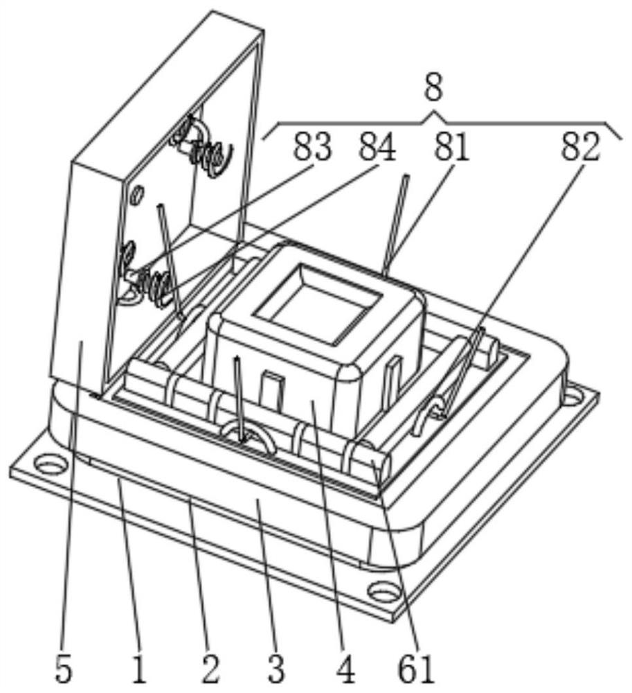
[0031] see Figure 1-2 , the present invention provides a technical solution: a two-way metering platform for power transmission lines, including a mounting plate 1, one side of the mounting plate 1 is evenly opened with mounting holes, one side of the mounting plate 1 is fixedly connected with a cooling frame 2, the cooling frame The outside of 2 is covered with an installation frame 3, the side of the installation frame 3 away from the heat dissipation frame 2 is fixedly connected to the main body 4 of the metering table, and the side of the installation frame 3 is rotatably connected to the sealing box 5, and the outside of the installation frame 3 is provided with:

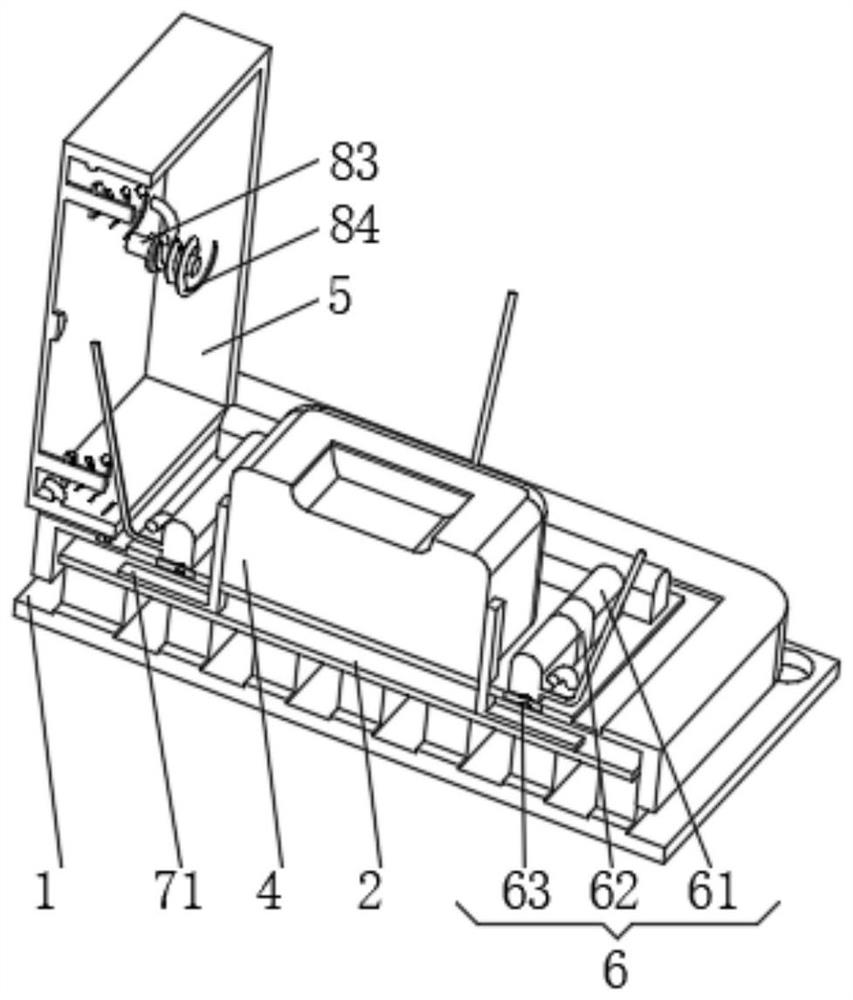
[0032] Flame retardant device 6, the flame retardant device 6 has a flame retardant bag 61, the inside of the flame retardant bag 61 is filled with dry powder fire extinguishing agent, the outside of the flame retardant bag 61 is provided with a limit bar 62, the limit bar 62 is made of plastic film material, ...

Embodiment 2

[0036] see Figure 1-5 , the present invention provides a technical solution: on the basis of Embodiment 1, an opening and closing device 7 is provided outside the installation frame 3, and the opening and closing device 7 has a heat conduction sheet 71, and the heat conduction sheet 71 is fixedly connected with the main body 4 of the metering platform, The heat conduction sheet 71 runs through the installation frame 3 and extends to the top of the heat dissipation frame 2 , and an air bag 72 is fixedly connected under the heat conduction sheet 71 .

[0037] The top of the heat dissipation frame 2 is provided with a functional groove 9 that is compatible with the inflatable bag 72. The functional groove 9 runs through the heat dissipation frame 2. A pressure platform 10 is slidably connected between the two sides of the inner wall of the functional groove 9. The bottom of the pressure platform 10 A pressure-bearing spring 11 is installed symmetrically, and one end of the press...


PUM


Abstract

The invention discloses a bidirectional metering table for a power transmission line. The bidirectional metering table comprises a mounting plate, wherein mounting holes are uniformly formed in one side of the mounting plate, a heat dissipation frame is fixedly connected to one side of the mounting plate, and a mounting frame externally sleeves the heat dissipation frame; a metering table main body is fixedly connected to the side, away from the heat dissipation frame, of the mounting frame, a sealing box is rotationally connected to one side of the mounting frame, a flame-retardant device is arranged outside the mounting frame and is provided with a flame-retardant bag, and a limiting strip sleeves the flame-retardant bag; an opening and closing device which is provided with a heat conducting sheet, wherein the heat conducting sheet is fixedly connected with the metering table main body; and a protection device which is provided with a traction rope. The present invention relates to the technical field of power transmission metering. According to the bidirectional metering table for the power transmission line, the purpose of improving the flame retardant capacity is achieved, fire can be extinguished in time when a fire behavior is generated, the heat dissipation mode of the device is increased, and the heat dissipation capacity of the device is improved.

Description

technical field [0001] The invention relates to the technical field of power transmission metering, in particular to a bidirectional metering platform for power transmission lines. Background technique [0002] At present, there are generally two methods for the grid connection of household distributed energy generation. One is the grid connection scheme under the policy of "on-grid electricity price, unified purchase and sales". This method is to connect the PV meter in front of the user's meter ), it is necessary to adopt a dual-meter grid-connected measurement scheme, and the other is a grid-connected scheme under the "net electricity metering" policy. This scheme measures the power generation and consumption of distributed power plants for a long period of time. , both need to be measured by double meters, and the use of two meters not only increases the cost, but also requires a larger space, while increasing the failure rate and maintenance costs, so the application ra...

Claims


Application Information

Patent Timeline
IPC IPC(8): G01R11/04A62C3/16A62C35/10H05K7/20
CPCG01R11/04A62C3/16A62C35/10H05K7/2039H05K7/20136
Inventor 何洋
Owner 何洋
Why Eureka
Try Eureka