Optical lens and imaging device

A technology of optical lens and imaging surface, which is applied in the field of imaging lens, can solve the problems of not being able to bring visual experience to consumers, the large size of the front camera head, and the difficulty of increasing the screen ratio, etc., to achieve compact structure, miniaturization, The effect of meeting the needs of use

Active Publication Date: 2021-12-14
JIANGXI LIANYI OPTICS CO LTD
View PDF8 Cites 2 Cited by
  • Summary
  • Abstract
  • Description
  • Claims
  • Application Information

AI Technical Summary

Problems solved by technology

In recent years, the continuous development of special-shaped screens such as water drop screens, notch screens, and hole-digging screens are all due to consumers' keen pursuit of full-screen mobile phones; due to the existence of the front camera and the excessive size of the head, the full-screen There are still many obstacles to the realization of
The outer diameter of the head of the optical lens commonly used in the market is as small as ∅3mm. Due to the larger outer diameter and overall volume of the head, it is difficult to increase the screen ratio and cannot bring consumers better visual experience

Method used


Image

  • Optical lens and imaging device
  • Optical lens and imaging device
  • Optical lens and imaging device

Examples


no. 1 example

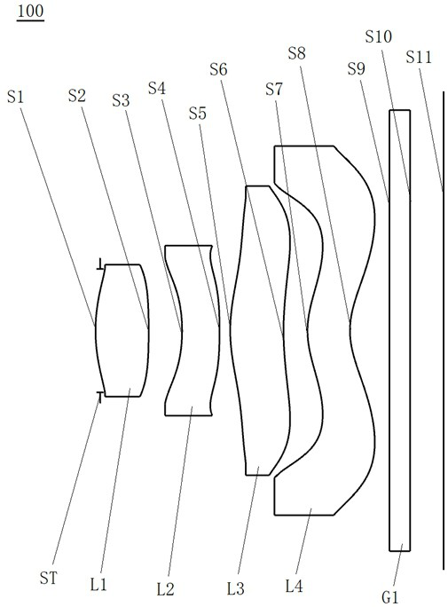
[0077] see figure 1 , which is a schematic structural view of the optical lens 100 provided in the first embodiment of the present invention, the optical lens 100 includes a stop ST, a first lens L1, a second lens L2, a third lens Lens L3, fourth lens L4 and filter G1.

[0078] Wherein, the first lens L1 has positive refractive power, the object side S1 of the first lens is a convex surface, and the image side S2 of the first lens is a convex surface;

[0079] The second lens L2 has negative refractive power, the object side S3 of the second lens is concave, and the image side S4 of the second lens is convex;

[0080] The third lens L3 has positive refractive power, the object side S5 of the third lens is convex at the near optical axis, and the image side S6 of the third lens is concave at the near optical axis;

[0081] The fourth lens L4 has positive refractive power, the object side S7 of the fourth lens is a convex surface at the near optical axis, the image side S8 of ...

no. 2 example

[0091] Such as Figure 5 As shown, it is a schematic structural diagram of the optical lens 200 provided by this embodiment. The optical lens 200 of this embodiment is substantially the same as that of the above-mentioned first embodiment, and the difference mainly lies in different design parameters.

[0092] Specifically, the design parameters of the optical lens 200 provided in this embodiment are shown in Table 3.

[0093] table 3

[0094]

[0095] In this embodiment, the aspheric parameters of each lens in the optical lens 200 are shown in Table 4.

[0096] Table 4

[0097]

[0098] Please refer to Figure 6 , Figure 7 and Figure 8 , showing the f-tanθ distortion curve, field curvature curve, and vertical axis chromatic aberration curve of the optical lens 200 respectively, from Figure 6 It can be seen that the optical distortion is controlled within ±1%, indicating that the distortion of the optical lens 200 has been well corrected; from Figure 7 It can ...

no. 3 example

[0100] Such as Figure 9 As shown, it is a schematic structural diagram of the optical lens 300 provided by this embodiment. The optical lens 300 of this embodiment is substantially the same as that of the above-mentioned first embodiment, and the difference mainly lies in different design parameters.

[0101] Specifically, the design parameters of the optical lens 300 provided in this embodiment are shown in Table 5.

[0102] table 5

[0103]

[0104] In this embodiment, the aspheric parameters of each lens in the optical lens 300 are shown in Table 6.

[0105] Table 6

[0106]

[0107] Please refer to Figure 10 , Figure 11 and Figure 12 , showing the f-tanθ distortion curve, field curvature curve, and vertical axis chromatic aberration curve of the optical lens 300 respectively, from Figure 10 It can be seen that the optical distortion is controlled within ±2%, indicating that the distortion of the optical lens 300 has been well corrected; from Figure 11 It c...


PUM


Abstract

The invention discloses an optical lens and imaging equipment. The optical lens sequentially comprises the following components from an object side to an imaging surface along an optical axis: a diaphragm; a first lens having positive power, wherein the object side surface of the first lens is a convex surface, and the image side surface of the first lens is a convex surface; a second lens having negative power, wherein the object side surface of the second lens is a concave surface, and the image side surface of the second lens is the convex surface; a third lens having the positive power, wherein the object side surface of the third lens is the convex surface near the optical axis, and the image side surface of the third lens is the concave surface near the optical axis; a fourth lens having the positive power, the object side surface of the fourth lens is the convex surface near the optical axis, the image side surface of the fourth lens is the concave surface near the optical axis, and the object side surface and the image side surface of the fourth lens are respectively provided with at least one inflection point; wherein the entrance pupil diameter EPD of the optical lens is less than 1.4 mm; and the optical lens satisfies the following conditional expressions: CT1 / TTL is greater than 0.12 and less than 0.35; wherein CT1 represents the center thickness of the first lens, and TTL represents the total optical length of the optical lens. The optical lens has the advantages of high pixel, miniaturization and low sensitivity.

Description

technical field [0001] The invention relates to the technical field of imaging lenses, in particular to an optical lens and imaging equipment. Background technique [0002] At present, with the popularity of portable electronic devices and the popularity of social networking, video, and live broadcast software, people are more and more fond of photography. Camera lenses have become standard equipment for electronic equipment, and camera lenses have even become consumer It is the index that consumers consider first when purchasing electronic equipment. [0003] With the continuous development of mobile information technology, portable electronic devices such as mobile phones are also developing in the direction of ultra-thin, full-screen, ultra-high-definition imaging, etc., which puts forward higher requirements for camera lenses mounted on portable electronic devices , not only must have sufficient optical performance and imaging capabilities, but also have a certain aesth...

Claims


Application Information

Patent Timeline
IPC IPC(8): G02B13/00G02B13/18G03B30/00
CPCG02B13/004G02B13/18G03B30/00
Inventor 章彬炜钟培森曾昊杰
Owner JIANGXI LIANYI OPTICS CO LTD
Why Eureka
Try Eureka